IEPE accelerometer

Single-axis vibration. Standard IEPE output.

Request a quotation
iQunet stainless-steel IEPE accelerometer with two-pin MIL connector
Case-isolatedHermetically sealed

Piezoelectric sensing for rotating machinery

Measure vibration on motors, pumps and gearboxes with a rugged stainless-steel sensor. Use your existing IEPE acquisition system, or add the iQunet bridge for wireless recording and analysis on the M4.

Sensitivity
100 mV/g ±10%
Dynamic range
80 g peak
Sensor temperature
−55 to +120 °C

Add wireless acquisition with iQunet

Mount the accelerometer on the machine and place the bridge where power and radio coverage are available. A shielded cable carries the IEPE signal to the acquisition module inside.

IEPE accelerometer

iQunet stainless-steel IEPE accelerometer with two-pin MIL connector

One measurement axis

Wireless Sensor Bridge

IEPE AD module that fits inside the Wireless Sensor Bridge
IEPE AD moduleExcitation & digitisation
24 V DC
Explore the module

Edge Gateway M4

With iQunet radio interface

Local storage & analysis
Explore the M4

One module per sensor

A bridge accepts up to three AD modules. Equip one measurement point now and add channels as needed.

Place the bridge separately

Choose a 5 m, 10 m or 15 m shielded cable to suit the route from the machine to the bridge.

Record the waveform. Explore its spectrum.

Set the recording interval and capture length from the dashboard. Inspect impacts in the time waveform, follow frequency components in the FFT spectrum and compare recordings in waterfall plots.

With the IEPE AD module32–8,192 samples per recording

Choose the recording rate and filtering for the frequencies you want to investigate.

Vibration ExpertGear mesh & sideband analysis
Software example · Recorded spectrum and measurement history. Click to enlarge.

Vibration Expert

Keep recordings on the M4 and export samples for further analysis in your own software.

Monitoring & analysis

Technical details

Measurement specs

Installation

Product data

Datasheet PDF
Are channels in one bridge synchronised?

Each IEPE AD module records one channel using its own acquisition clock. A bridge can contain three modules, but their recordings are not phase-synchronised. For a measurement that requires cross-channel phase, discuss the acquisition setup with us.

Request a quotation

IEPE accelerometer

Tell us about the measurement point. We’ll help specify the sensor, cable and acquisition hardware.

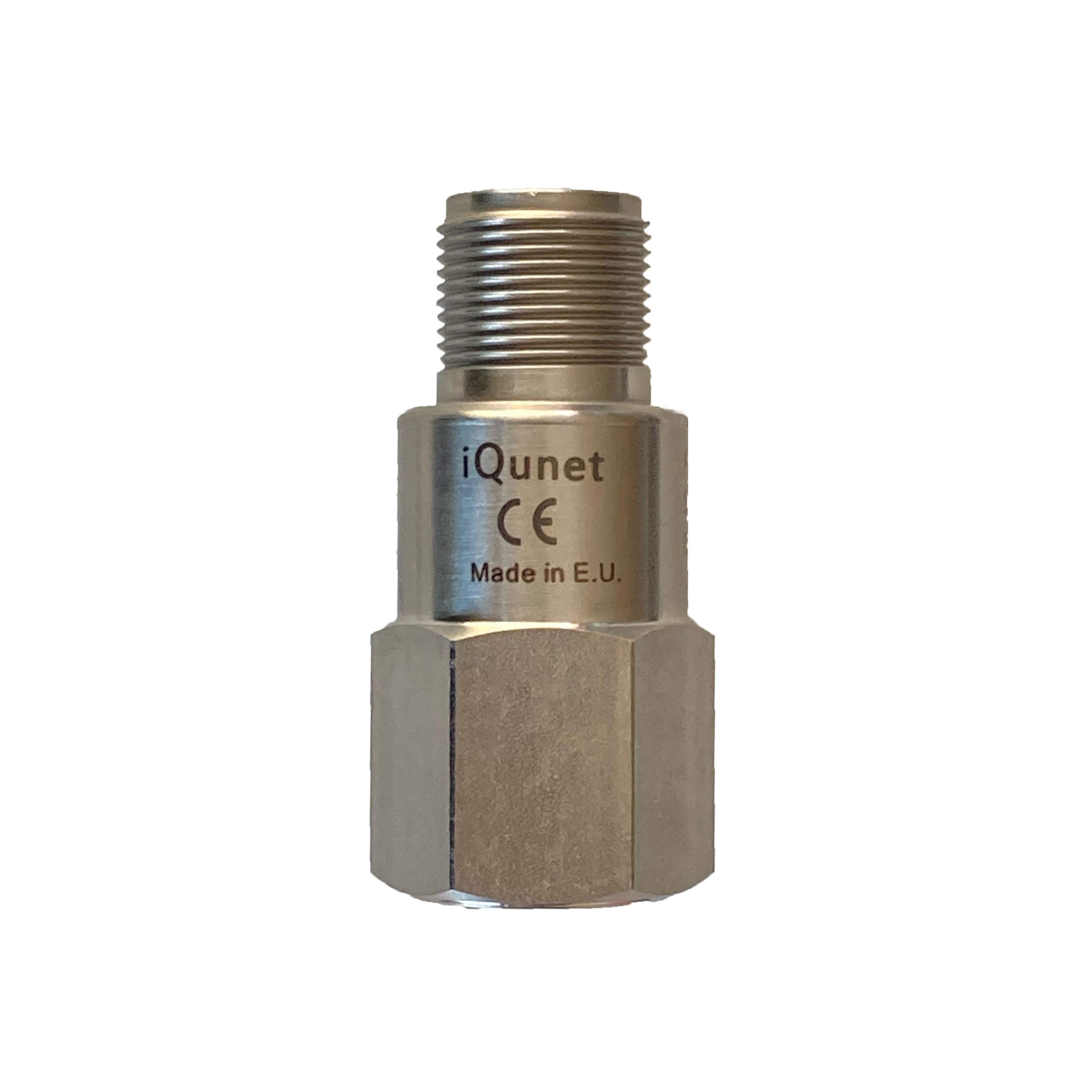
iQunet stainless-steel IEPE accelerometer with two-pin MIL connector

€229.40 per sensorExcl. VAT & shipping. Configuration confirmed with your quotation.

IEPE accelerometer

Technical details

Sensor response

IVIB251120-IEPE-T1AX is a single-axis annular-shear piezoelectric accelerometer. These ratings describe the sensor; the acquisition system sets the recorded frequency band.

Sensitivity
100 mV/g ±10%
Dynamic range
80 g peak
Frequency response
1–9,000 Hz (±10%); 0.5–14,000 Hz (±3 dB)
Mounted resonance
25 kHz nominal
Linearity
±1% maximum
Measurement
One vibration axis

For an existing IEPE acquisition system, select 100 mV/g sensitivity and a suitable recording bandwidth. The sensor uses constant-current excitation over the same two wires as its voltage signal.

PDFIEPE accelerometer datasheet

Recording with the IEPE AD module

Each BRID211010-ADMOD-IEPE module excites and digitises one accelerometer. Configure the recording from the dashboard and analyse the transferred samples on the M4.

Exported sampling rate
Nominal 4–4,000 samples/s, selectable
Recording length
32–8,192 samples per channel
Sensor sensitivity
Selectable 10, 100, 500 or 1,000 mV/g; use 100 mV/g for this sensor
Capture
Programmable recording interval or manual request
Analysis
Time waveform, FFT spectrum, waterfall, RMS and kurtosis; sample export
Units
Acceleration in g or calculated velocity in mm/s

Recording rate and filter bandwidth

The highest nominal rate exports approximately 3,906 samples/s. The ADC digital filter has a −3 dB corner of about 480 Hz at that setting. Its filter response, the sensor and mounting all affect the recorded signal. The sensor’s 9 kHz response rating is separate from this acquisition path.

PDFIEPE AD module datasheetExplore the IEPE AD module

Mounting & cable

Stud-mount the sensor on a prepared, rigid measurement surface. Use a shielded two-pin MIL cable to connect the sensor to the IEPE input, and secure the cable near the measurement point.

Sensor connector
Two-pin MIL glass-seal hermetic connector
Cable lengths
5 m, 10 m and 15 m options; blunt-cut bridge end
Sensor temperature
−55 to +120 °C
Standard cable temperature
−30 to +90 °C
Module and bridge temperature
−10 to +50 °C
Ground isolation
Dual-case isolation with an internal Faraday shield; 100 MΩ minimum case-to-shield isolation

Keep the bridge and cable within their own temperature ratings when the sensor is mounted on a hot or cold machine surface.

PDFIEPE cable datasheetCable options

Wireless Sensor Bridge connection

The accelerometer connects by cable to an IEPE AD module inside the bridge. The bridge sends measurements over the iQunet radio network to an M4 with a compatible radio interface.

Capacity
Up to three AD modules, one sensor channel per module
Power
24 V DC; the 5.1 V / 15 W micro-USB alternative is limited to IEPE and compatible current-clamp configurations
Enclosure
IP66/67 bridge enclosure; the plug-in AD module has no standalone ingress protection
Module temperature
−10 to +50 °C
Channel timing
Each AD module uses its own acquisition clock; separate channels are not phase-synchronised
Data access on the M4
Browser analysis, sample export, OPC UA, MQTT, GraphQL and OpenAI MCP

Select matching radio hardware for the installation. Sensors, cables and AD modules are separate components.

PDFWireless Sensor Bridge datasheetWireless network components

Sensor specifications

IVIB251120-IEPE-T1AX · Datasheet D1369

Construction
AISI 316L stainless steel, hermetically sealed
Weight
85 g
Dimensions
50.8 mm high; 22 mm hex body; see drawing for connector dimensions
Excitation
4 mA nominal constant current; 2–10 mA DC permitted
Supply compliance
22–28 V DC, through an IEPE constant-current source
Output bias
12 V DC nominal at 4 mA
Output impedance
50 Ω nominal
Warm-up time
Less than 1 second
Shock limit
5,000 g peak
Continuous vibration limit
500 g peak

The shock and continuous-vibration limits describe mechanical survival. The measurement range is 80 g peak.

Datasheets

PDFIEPE accelerometer datasheetPDFIEPE Vibration AD Module datasheetPDFWireless Sensor Bridge datasheetPDFIEPE cable datasheet
iQunet · Engineering enquiries

Ask us a question

Ask about our products or pricing, request a demonstration, or get technical help.

About your question

About: IEPE accelerometer

Request type: General question
Prefer email or a call?info@iqunet.com+32 52 86 00 25

We use your details to answer this request. Privacy information (new tab)
