

Overview#
ModVibe is an IP67/IP68-rated industrial vibration sensor with two triaxial accelerometers and integrated temperature monitoring. It records acceleration waveforms and transfers them over Modbus RTU for continuous or periodic machine-condition monitoring.
Key features#
Triaxial acceleration waveform acquisition
Selectable low-noise ranges of , , and
Selectable wideband ranges of , , and
8 kS/s low-noise path or 16 kS/s wideband path, selectable for each capture
On-board dual-core Arm Cortex-M33 processor with DSP and floating-point support for complex filtering operations
On-board Type I low-pass FIR decimation to 125 S/s for triaxial capture windows of approximately 1 min
Integrated MEMS sensor temperature monitoring and firmware health diagnostics
Wide 12–30 VDC input range; 24 VDC nominal
IP67/IP68-rated enclosure for industrial installation
2-wire RS-485 with Modbus RTU at 115.2k baud; optional 230.4k or 460.8k baud transfer boost
Integrated bootloader for firmware updates over Modbus RTU
Engineering option: application-specific firmware available on request
Applications#
Predictive maintenance for motors, pumps, fans, gearboxes, and compressors
Permanently installed acquisition for slow-speed and broadband machine diagnostics
Vibration sensor characteristics#
| Characteristic | Low-noise | Wideband |
|---|---|---|
| Sensor | ADXL380 | ADXL382 |
| Measurement axes | X/Y/Z | X/Y/Z |
| Selectable range | ||
| Noise density, X/Y/Z* | ||
| Sensor bandwidth ( dB)† | 4 kHz | 8 kHz |
| Nominal counts/g, lowest range | 7500 | 2000 |
| PDM stream | 1-bit, 32 kS/s | 1-bit, 64 kS/s |
| TDM stream | 16-bit, 8 kS/s | 16-bit, 16 kS/s |
*Characteristic values measured during finished-device characterization.
† dB corner in high-performance mode with default sensor filters.
System overview#
ModVibe acquires triaxial acceleration time waveforms using either its low-noise or wideband vibration sensor. It filters, buffers, and transfers each waveform over Modbus RTU.
Both on-board MEMS sensors generate a 1-bit PDM stream at up to 64 kS/s. Third-order sinc decimation integrates the complete stream into 16-bit acceleration samples at 8 kS/s for the ADXL380 and 16 kS/s for the ADXL382. These source streams feed the Modbus waveform interface.
Firmware applies FIR decimation when required, buffers the completed waveform in SRAM, and returns the X, Y, and Z axis blocks over Modbus RTU. The interface also reports sensor temperatures, device identity, and diagnostics.
Populated magnetic-field hardware is reserved for future rotational-speed measurement and other magnetic-field applications.
This datasheet follows the complete ModVibe measurement chain, from defining the required vibration content and selecting the sensing path to waveform transfer and mechanical mounting. Sections 1 and 2 provide hands-on guidance for configuring and retrieving a measurement.
The supporting concepts are introduced along the way, where they are needed. Sections 3–6 then cover temperature and diagnostic information, electrical integration, and device installation.
Functional block diagram#
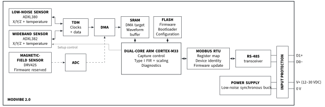
Capture setup#
ModVibe combines two triaxial vibration sensors with complementary measurement roles. The ADXL380 low-noise path targets lower-range measurements; the ADXL382 wideband path covers higher frequencies and acceleration levels. A capture setup is the combination of sensor, full-scale range, output rate, and samples per axis used for one measurement.
Firmware compatibility
For this document, require the exact application firmware 1.03 tuple: identity contract 2, register-map contract 3, capture API version 5, data-window contract 3, and FIR catalog 3. Registers 9–10 report the 32-bit firmware version, high word first; version 1.03 is
0x00000103. Reject mixed tuples and do not infer compatibility from a later version.
Define the measurement requirements#
Define the vibration content by answering three questions: What is the highest relevant frequency? What is the largest expected peak acceleration? How long must the observation be to capture the slowest behavior or a complete transient? The table summarizes the main configuration trade-offs [8]. Section 1.5 examines sample rate, record duration, and noise together in detail.
| Setting | Choice | Result |
|---|---|---|
| Sensor | ADXL380 | Lower noise; 3.8 kHz usable bypass bandwidth and range |
| Sensor | ADXL382 | 7.6 kHz usable bypass bandwidth and range |
| Output rate | Lower | Longer observation and lower bin noise; reduced usable bandwidth |
| Full-scale range | Lower | Finer nominal scaling; reduced clipping margin |
| Sample count | Higher | Finer frequency resolution and lower bin noise; longer capture and transfer |
Select the vibration sensor#
ADXL380 LOW-NOISE [1]
Select this sensor when the required measurement range does not exceed and content above 4 kHz is not required.
Typical uses include shaft-speed harmonics on slow-running motors, paper-machine rollers, and conveyors. At 125 S/s and , the characterized noise-density value corresponds, under a white-noise model, to an estimated noise-only full-scale sine SNR of 84 dB (13.7-bit ideal-ADC equivalent).
ADXL382 WIDEBAND [2]
Select this sensor when the required range is or , or when relevant content above 4 kHz may be present.
Typical uses include bearing-impact, gear-mesh, and pump-cavitation measurements.
Range selection: SNR versus clipping#
Select the lowest full-scale range that accommodates the largest expected peak acceleration, including transient shocks and gravity.
Gravity component
The returned waveform is DC-coupled, so each axis contains both vibration and the projected gravity component. Depending on mounting orientation, gravity can contribute up to 1 g on an axis.
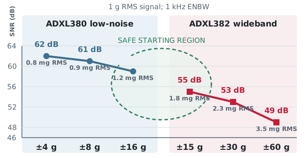
Clipping distorts the time waveform and introduces false harmonic content into the spectrum. As a practical starting point, use on the ADXL380 or on the ADXL382. These adjacent ranges form the crossover between the low-noise and wideband paths. Increase the range if peaks may exceed this initial limit.
For the ADXL380, select or only after a capture confirms sufficient peak margin. The lower ranges are justified mainly for long, reduced-bandwidth measurements, where filtering lowers integrated noise. For the raw bypass ADXL380 vibration data, MEMS noise remains above quantization noise at every range.
Figure 1 compares every range for a 1 g RMS signal in a 1 kHz equivalent noise bandwidth, using the Table 4 characterization values under a white-noise model.
FIR response and usable bandwidth#
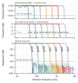
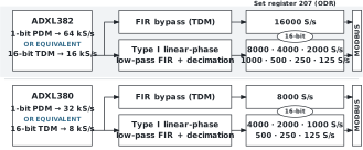
ModVibe 2 applies an embedded FIR low-pass filter before decimation. Reduced output rates use fixed profiles; full-rate ADXL380 (8 kS/s) and ADXL382 (16 kS/s) captures bypass the filter.
The Modbus waveform interface supports two analysis paths:
Shaft orders and low-frequency motion: retain characteristic harmonics for low-noise, high-resolution analysis of imbalance, misalignment, and looseness.
Impacts and envelopes: capture high-frequency resonances excited by early bearing defects, localized cracking, and other impacts.
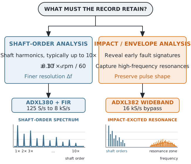
ADXL380 + FIR: Typical shaft-order signatures include dominant radial 1 vibration from imbalance, elevated axial 1 or radial 2 vibration from misalignment, and running-speed harmonic trains from mechanical looseness. For this analysis, use the ADXL380 with the lowest waveform rate that preserves the required orders with adequate bandwidth margin.
ADXL382: Bearing and gear faults excite high-frequency machine resonances. The higher sample rate of the ADXL382 captures these resonances and preserves the impact waveform. Envelope analysis then demodulates the resonance band to recover the baseband fault frequency. Use the ADXL382 when 16 kS/s waveform capture is required.
The linear-phase FIR profiles preserve waveform shape, reach dB near , and fall below dB at ; see Figure 3. The FIR dB passband listed in Table 1, not the output Nyquist frequency, defines the usable analysis bandwidth.
Slow-speed machinery
At a fixed number of samples , a lower waveform rate extends the record so it spans more shaft revolutions. This gives finer FFT frequency resolution without increasing the waveform transfer payload. Section 1.5 applies this trade to representative machinery.
Output-rate selection
For envelope analysis, use the upper edge of the resonance carrier band. In practice, select the ADXL382 at 16 kS/s bypass and , increasing the range only when peak acceleration requires more headroom. An ADXL382 capture can also augment an ADXL380 measurement by revealing significant content above 4 kHz.
Balancing sample rate, duration, and noise#
For a fixed sample count , FIR filtering and decimation link usable bandwidth, record duration , and FFT-bin spacing : A lower output rate therefore gives a longer observation and narrower FFT bins, while a higher rate preserves higher-frequency content. For approximately white noise and a fixed FFT window, halving the FFT-bin equivalent noise bandwidth (ENBW) reduces the noise power per FFT bin by 3 dB, making narrow spectral lines easier to detect.
For shaft-order analysis, the highest required frequency is Here, is the highest shaft order to retain.
Select the lowest mode in Table 1 whose FIR dB band contains .
Table 1. FIR bandwidth and recommended output rate.
| Rate | FIR 3 dB | FIR 60 dB | ADXL380 | ADXL382 |
|---|---|---|---|---|
| 125 | 45 Hz | 62.5 Hz | FIR | (FIR) |
| 250 | 90 Hz | 125 Hz | FIR | (FIR) |
| 500 | 181 Hz | 250 Hz | FIR | (FIR) |
| 1k | 362 Hz | 500 Hz | FIR | (FIR) |
| 2k | 723 Hz | 1 kHz | FIR | (FIR) |
| 4k | 1.4 kHz | 2 kHz | FIR | (FIR) |
| 8k | 2.9 kHz | 4 kHz | bypass 3.8 kHz | FIR |
| 16k | – | – | – | bypass 7.6 kHz |
Rate is the waveform sample rate [S/s]; bandwidth columns apply only to FIR modes. Parentheses mark a supported but nonrecommended FIR mode. Bypass bandwidth follows the typical equalized-flatness limit specified in the ADXL380 and ADXL382 data sheets [1, 2].
For a 300 rpm shaft retaining orders through , the highest required frequency is Hz. The 125 S/s profile is too narrow because its dB bandwidth is 45 Hz. Select 250 S/s, whose 90 Hz bandwidth provides 40 Hz of margin.
Impact-excited bearing and gear resonance bands lie outside the 90 Hz dB passband of the 250 S/s FIR and still require ADXL382 at 16 kS/s for envelope analysis.
Why downsampling matters#
At , the 250 S/s capture lasts 32.8 s, has Hz, and spans about 164 shaft revolutions. A 16 kS/s capture with the same payload lasts only 0.512 s and spans about 2.6 revolutions.
A record containing only two complete revolutions provides too little repeated motion for stable shaft-order amplitudes, fine spectral separation, or resolving slow amplitude modulation of the 1 component. A lower-rate recording observes the motion over many revolutions, while the waveform payload size and download time remain unchanged.
| Zone | Representative application | rpm | ODR mode | 1 noise (m/s RMS) | |
|---|---|---|---|---|---|
| A | Wind-turbine rotor | 125 S/s FIR | 66 s | ||
| B | Conveyor shaft | 300 | 250 S/s FIR | 1.7 | 33 s |
| C | Fan or pump | 600 | 500 S/s FIR | 1.2 | 16 s |
| D | 4-pole motor | 1500 | 1 kS/s FIR | 0.69 | 8 s |
| E | 2-pole motor | 3000 | 2 kS/s FIR | 0.49 | 4 s |
| F | Compressor shaft | 6000 | 4 kS/s FIR | 0.35 | 2 s |
| G | High-speed compressor | up to 46k | 16 kS/s bypass | 0.20 | 0.5 s |
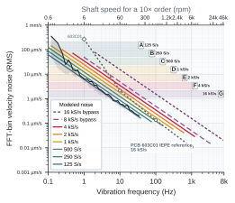
Figure 4 places this rule in an application context. Start with the application table above the graph and select a close operating case.
Each row links an example application to a zone (A–G) and recommended ODR mode. At , it also gives record duration and modeled FFT-bin velocity noise at the application’s 1 frequency, in m/s RMS. For another spectral line, read the graph at the required frequency to estimate detection sensitivity.
Comparison with piezo sensors#
Figure 4 compares modeled ModVibe FFT-bin velocity noise with published PCB 603C01 sensor noise [3, 4]. The 603C01 curve excludes signal-conditioning and digitizer noise.
For a fair comparison, the 603C01 reference assumes an external 16 kS/s acquisition with , matching the ADXL382 record duration and Hann RBW. Lower-rate ModVibe modes retain the same payload and transfer time while FIR decimation lengthens the record and narrows its RBW.
The modeled FFT-bin velocity-noise performance is similar through the 1 kS/s ModVibe FIR mode. At higher rates, the PCB 603C01 has the lower modeled noise floor. ModVibe additionally provides dc response, synchronized triaxial acquisition, and long low-rate records.
PIEZOELECTRIC
Flat acceleration noise appears as -shaped equivalent velocity noise because the conversion divides by . Below its specified 0.5 Hz (30 rpm) low-frequency limit, the PCB 603C01 response rolls off.
MEMS
ModVibe retains dc response. The preliminary 125 S/s measurement shows increasing colored noise and drift below approximately 0.5 Hz, with additional influence from bias drift and temperature sensitivity. The black trace in Figure 4 shows this measured behavior.
Table 2. Waveform capture and download registers.
| PDU addr. | Setting | Access | Data type | Value / format |
|---|---|---|---|---|
| 200 | Capture API version | R/O | UINT16 | 5 |
| 201 | Data-window version | R/O | UINT16 | 3 |
| 202 | Capture status | R/O | UINT16 enum | 0 = IDLE; 1 = CONFIGURED; 2 = ACQUIRING; 3 = PROCESSING; 4 = READY; 5 = ERROR |
| 203 | Capture error | R/O | UINT16 enum | 0 = NONE; 1–13 = error code; see Appendix A |
| 204 | Start/reset control | R/W | UINT16 enum | 0 = IDLE/reset; 1 = START |
| Write setup registers 205–213 together with Modbus FC16 (Write Multiple Registers) | ||||
| 205 | Sensor select | R/W | UINT16 enum | 2 = ADXL380; 3 = ADXL382 |
| 206 | Axis bitmask | R/W | UINT16 bit field | 0x07 = X/Y/Z (required) |
| 207 | Output rate | R/W | UINT16 | Sensor-dependent; see Section 1.6 |
| 208–209 | Samples per axis | R/W | UINT32 | HI 208 LO 209; values 64, 128, 256, 512, 1024, 2048, 4096, or 8192 |
| 210 | Signal processing chain | R/W | UINT16 enum | 0x03 = automatic source-rate FIR or full-rate bypass (required) |
| 211 | Enforce transfer-time budget | R/W | UINT16 enum | 1 = enabled (required) |
| 212 | Waveform transfer budget | R/W | UINT16 | 30000 ms |
| 213 | Full-scale range | R/W | UINT16 | Write 4/8/16 for 4/8/16 g on ADXL380. Write 15/30/60 for 15/30/60 g on ADXL382. |
| Read result registers 214–220 after CAPTURE_STATUS reports READY | ||||
| 214–215 | Total waveform words | R/O | UINT32 | HI 214 LO 215; total words in the X/Y/Z payload |
| 216–217 | Total download pages | R/O | UINT32 | HI 216 LO 217; total 122-word payload pages |
| 218–219 | Estimated download time | R/O | UINT32 | HI 218 LO 219; milliseconds at the normal transfer rate |
| 220 | Waveform ID | R/O | UINT16 | Identifies the committed waveform |
| Download registers | ||||
| 228–229 | Window offset | R/W | UINT32 | HI 228 LO 229; zero-based payload-word offset; write with FC16 |
| 1000 | Page waveform ID | R/O | UINT16 | Copy of register 220 for page validation |
| 1001–1002 | Returned offset | R/O | UINT32 | HI 1001 LO 1002; must match registers 228–229 |
| 1003–1124 | Waveform payload | R/O | INT16 array | Up to 122 waveform words; final page is zero-padded |
See Appendix A for the complete register map.
Addresses are zero-based Modbus PDU addresses.
Data-order conventions are defined in Section 5.6.
This table requires the exact ModVibe application firmware 1.03 tuple: identity contract 2, application version 0x00000103, register-map contract 3, capture contract 5, data-window contract 3, and FIR catalog contract 3. Do not infer compatibility from a later version.
ModVibe waveform configuration#
With the sensor, range, ODR, and record length selected as described in Sections 1.2–1.5, write the waveform configuration to registers 205–213.
Note
All registers referenced in this section are listed in Table 2.
Sensor and axes. Set register 205 to 2 for the ADXL380 or 3 for the ADXL382. Set the axis bitmask in register 206 to 0x07 (all axes enabled).
Write the full-scale range. Set register 213 to 4, 8, or 16 for the ADXL380, or to 15, 30, or 60 for the ADXL382. The written value specifies the positive full-scale magnitude; for example, 8 selects a range of .
Output rate and processing. Write the selected output rate in S/s to register 207. Set register 210 to 0x03 so firmware selects the FIR or bypass path corresponding to the selected sensor and output rate, as shown in Figure 5.
Samples per axis. Write the 32-bit sample count to registers 208–209, high word first. Register 208 is 0, and register 209 contains the selected count. Supported counts are , 128, 256, 512, 1024, 2048, 4096, and 8192 samples per axis.
With samples per axis and output sampling frequency , the nominal record duration is . Table 3 gives example configurations and their resulting duration and bandwidth. X/Y/Z are acquired simultaneously, so the axis count does not multiply the record duration.
Table 3. Example settings: FIR dB; bypass flatness.
| Application | Sensor | rpm (10) | ODR [S/s] | Analysis BW | ||
|---|---|---|---|---|---|---|
| Slow shaft order | ADXL380 | 250 | 8192 | 33 s | 90 Hz | |
| General shaft order | ADXL380 | 500–4000 | 2k | 8192 | 4 s | 723 Hz |
| Impact / envelope | ADXL382 | – | 16k | 8192 | 0.5 s | 7.6 kHz |
Download-time budget. Set register 211 to 1 and register 212 to 30000 ms. Section 2.1 explains how this budget is checked when a capture is started.
Write the complete configuration. Write registers 205–213 together in one Write Multiple Registers (FC16) request. This only arms the device for the next capture; Section 2.1 explains how to start it.
Complete an active download before reconfiguring Writing configuration registers 205–213 invalidates the current captured waveform in SRAM: CAPTURE_STATUS register 202 changes to CONFIGURED, the output word and page counts become zero, and subsequent page reads contain no valid waveform data.
Capture and download a waveform#
CONTROL and CAPTURE_STATUS registers#
To acquire a time waveform, the Modbus RTU client writes the complete sensor configuration described in Section 1.6 to the device, writes START (1) to the CONTROL register (204), and polls the CAPTURE_STATUS register (202) until it reports READY or ERROR (see flowchart Figure 6). Table 2 summarizes the configuration, status, and page-download registers used by this workflow.
When START is requested, firmware estimates the waveform download time before acquisition. If the estimate exceeds the 30 s budget configured in registers 211–212, acquisition does not start: CAPTURE_STATUS register 202 reports 5 (ERROR), and error-code register 203 reports 7 (DOWNLOAD_BUDGET_EXCEEDED).
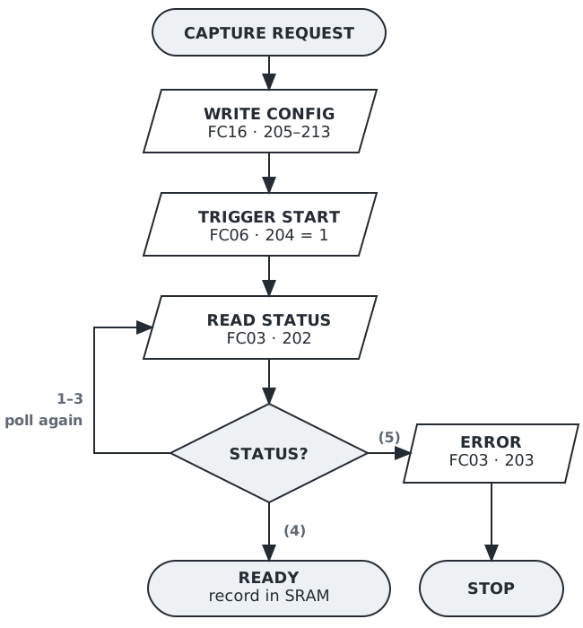
The capture request sequence uses FC06 (Write Single Register) for START and FC03 (Read Holding Registers) for status and error reads.
CAPTURE_STATUS reports READY only after the complete X/Y/Z waveform has been stored in SRAM and is available for download.
Valid CAPTURE_STATUS values are 0 through 5. Firmware reports an aborted capture as ERROR (5), with error-code register 203 set to ABORTED (12). Treat any CAPTURE_STATUS value above 5 as an incompatible firmware state.
Use the capture-duration formula in Section 1.6 to schedule the first status read. Then poll CAPTURE_STATUS (202) once per second until READY or ERROR. This reduces unnecessary bus traffic and allows the Modbus client to interleave captures across multiple sensors.
Time waveform record format#
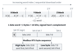
When CAPTURE_STATUS (202) reports READY, internal SRAM holds one complete X/Y/Z acceleration record. Each axis block contains chronological samples in X, Y, Z order.
The payload contains Modbus register words ( bytes). Each word stores one signed 16-bit two’s-complement (int16) sample. Modbus transmits the most-significant byte first; within each byte, UART transmits the least-significant bit first. Figure 7 shows the three-axis case and the sample-byte mapping.
Use Table 4 to convert each int16 sample code to acceleration in g for the selected sensor and full-scale range.
Table 4. Nominal conversion to g.
| Sensor | Full-scale | Scale factor (LSB/g) | Noise density* (g/) |
|---|---|---|---|
| ADXL380 | g | 7500 | |
| ADXL380 | g | 3750 | |
| ADXL380 | g | 1875 | |
| ADXL382 | g | 2000 | |
| ADXL382 | g | 1000 | |
| ADXL382 | g | 500 |
*Characteristic noise-density values measured during finished-device characterization. Scale factors are nominal and not shaker-calibrated.
Store the selected sensor, range, and output rate with each downloaded waveform; these values are not included in the returned data.
Samples are DC coupled and include the gravity component projected onto each axis. For zero-centered acceleration RMS, remove the record mean and apply any band limits required by the measurement. Before integrating acceleration to velocity, apply a high-pass filter with a cutoff below the lowest vibration frequency of interest; otherwise offset, drift, and low-frequency noise produce a wandering velocity baseline.
ModVibe 2.0 transfer boost Where cable length and bus loading permit, a compatible Modbus client can use the optional (nonstandard) boost mode at up to 460k baud, four times the nominal baud rate. Boost mode is covered in
Time waveform download procedure#
The Modbus client retrieves the completed record through the paged waveform data window (1000–1124). Each FC03 multi-word read uses the 125-register Modbus limit: three header registers contain the waveform ID and slice offset, followed by up to 122 waveform words.
The download procedure is as follows (Figure 8):
Read and store the READY metadata (214–220).
For each page, write the required offset in the SRAM record to registers 228–229 (UINT32), then read the 125 registers of the data window (1000–1124).
Validate the returned waveform ID (1000) and offset (1001–1002) against the READY metadata, then append up to 122 waveform words from registers 1003–1124.
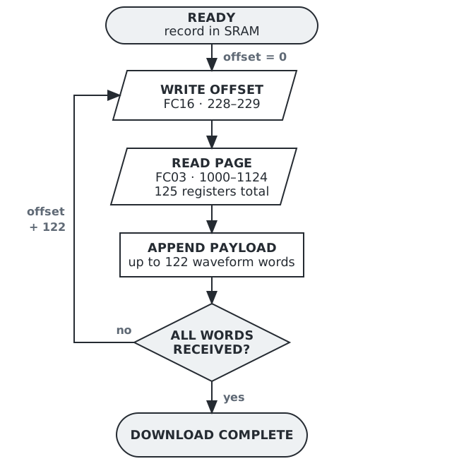
READY metadata (214–220)
Obtain the waveform word count, page count, and waveform ID. For samples per axis, expect words and pages.
Waveform ID (220)
Firmware auto-increments the waveform ID for each completed waveform recording, immediately before setting register 202 to READY. The ID wraps from 0xffff back to 0x01. Validate every page against the READY waveform ID.
Download duration. For , the X/Y/Z payload contains words. At 115.2k baud, firmware reports an estimated payload transfer time of about 24 s in registers 218–219.
Set the window offset (228–229)
The uint32 window offset specifies the zero-based word index in the SRAM waveform record. Write the high word followed by the low word in one Write Multiple Registers (FC16) request. Use page-aligned offsets 0, 122, 244, and so on, advancing only after each validated page. Firmware rejects other offsets to prevent off-by-one errors. Page reads do not auto-advance the offset.
Read and validate a page
Read all 125 holding registers at addresses 1000–1124 in one Read Holding Registers (FC03) request. Before concatenating waveform words, verify that the header waveform ID matches the READY waveform ID and the returned offset matches the requested offset. Firmware zero-pads the final page; discard the padding.
Continue or retry the download
For a complete download, continue until the page and word counts match those in the READY metadata (214–217). If a page read times out or fails the Modbus CRC check, simply rewrite the same offset and retry, up to a fixed limit.
Partial download of one axis (optional)
X, Y, and Z begin at word offsets 0, , and . Begin at the greatest multiple of 122 that does not exceed the selected block’s first-word offset, then continue through the page containing its last word. Discard words outside the selected axis. Use the same validation and retry rules.
Further reading Appendix A: ModVibe 2.0 Register Map defines paging, status, retry, boost, and recovery.
Appendix B: Capturing a ModVibe Waveform: Minimal Modbus RTU application note is a worked direct-capture example with executable code.
MEMS temperature#
Temperature registers#
Registers 48 and 49 report the scaled internal temperatures of the ADXL380 and ADXL382. Registers 50 and 51 provide the corresponding uncalibrated TDATA codes as defined in the sensor data sheets [1, 2].
These readings indicate the on-board sensor temperatures, not the instantaneous machine-surface temperature. They follow machine temperature through the enclosure and sensor packages with some thermal delay. Continuous acquisition increases local power dissipation and may slightly elevate the readings.
Table 5. MEMS temperature registers.
| PDU addr. | Register | Access | Data type | Value / format |
|---|---|---|---|---|
| 48 | ADXL380 temp. | R/O | INT16 | 0.1 C/count; 0x8000 = invalid |
| 49 | ADXL382 temp. | R/O | INT16 | 0.1 C/count; 0x8000 = invalid |
| 50 | ADXL380 raw | R/O | INT16 | Sign-extended 12-bit TDATA code |
| 51 | ADXL382 raw | R/O | INT16 | Sign-extended 12-bit TDATA code |
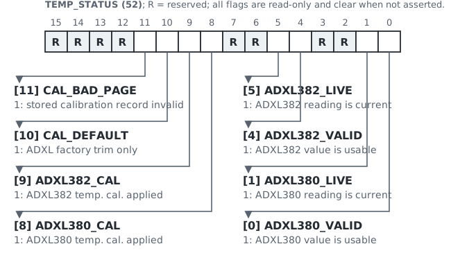
| 52 | Temp. status | R/O | UINT16 bit field | Validity and calibration flags; see Fig. 9 |
Temperature validity and freshness#
Before using a temperature value, check its VALID and LIVE bits in TEMP_STATUS (52). VALID means a usable cached value is stored; LIVE means the latest asynchronous refresh succeeded. Registers 48–54 return the cached snapshot immediately. A missing or stale snapshot queues one asynchronous refresh after the Modbus response; no sensor I2C occurs inline. Physical captures also request a refresh. Without temperature reads or physical captures, the cache can remain stale indefinitely. Use the AGE registers to apply the application’s freshness limit. A failed refresh preserves the last VALID value and its age but clears the affected LIVE bit. Do not infer validity from the scaled or raw code alone.
Firmware diagnostics#
Firmware validates the capture request, acquisition, READY record, and boost session:
Invalid capture request: START rejects an unsupported request, sets CAPTURE_STATUS (202) to ERROR, and publishes no waveform; ERROR (203) gives the cause.
Interrupted acquisition: READY follows a complete X/Y/Z record. Missing or discontinuous data reports SENSOR_FAULT; an FIR overrun reports PROCESS_OVERRUN.
READY record validation: an ID, word or page-count, or offset mismatch withdraws READY output and sets CAPTURE_STATUS (202) to ERROR.
Boost recovery: failed or abandoned sessions return to 115,200 bit/s. Routine fallback leaves no record; retained fields distinguish direct from software-reset recovery.
Health monitoring and fault response#
Registers 100–110 form the firmware health block summarized in Table 6. They report the current supervisor result and retain the most recent failed check and firmware response.
Table 6. Firmware health registers.
| PDU register addr. | Data type | Value / format | |
|---|---|---|---|
| 100 | HEALTH_CONTRACT | UINT16 | Require 0x01 |
| 101 | HEALTH_STATUS | UINT16 enum | 0 = OK; 1 = fault |
| 102–103 | RUN_COUNT | UINT32 | Supervisor run count |
| 104–105 | FAULT_COUNT | UINT32 | Failed supervisor checks |
| 106 | FAULT_BITS | UINT16 bit field | Latest-cycle fault mask |
| 107 | LAST_OWNER | UINT16 code | Service subsystem code |
| 108 | LAST_VALIDATOR | UINT16 code | Service check code |
| 109 | LAST_ACTION | UINT16 enum | Retained response |
| 110 | LAST_FAULT_BITS | UINT16 bit field | Retained fault mask |
HEALTH_CONTRACT (100)
The contract versions the layout and semantics of registers 101–110. Require 0x01 before interpreting them.
The 100 ms supervisor checks internal state for communication, acquisition, and transfer. Depending on the failed check, firmware:
repairs the state;
stops the affected operation in a safe error state; or
records the fault condition without changing the state.
HEALTH_STATUS (101) and FAULT_BITS (106)
Read registers 100–110 as one block. HEALTH_STATUS reports whether the latest supervisor cycle detected a fault. FAULT_BITS sets the corresponding subsystem bit for each fault found during that cycle. Figure 10 shows the summary status and maps each fault bit to its supervised area and firmware action.
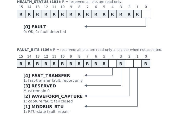
Use the health block
HEALTH_STATUS and FAULT_BITS report active faults and clear after a healthy supervisor cycle.
LAST_FAULT_BITS and LAST_ACTION preserve the most recent failure; nonzero retained values do not imply an active fault.
Poll RUN_COUNT more than 100 ms apart to confirm supervision; within one run, a FAULT_COUNT increase reveals failed checks between reads.
FAULT_BITS identifies the affected subsystem. Inspect the corresponding Modbus RTU, capture, or fast-transfer registers for detail; see Appendix A, Section 5 for health semantics and recovery.
Electrical and communication interface#
Operating limits#
| Parameter | Min. | Nom. | Max. | Unit |
|---|---|---|---|---|
| Input voltage at sensor | 12 | 24 | 30 | VDC |
| Operating temperature | C |
∗ Applies to ambient and mounting-interface temperature.
Electrical interface summary#
ModVibe connects through one fixed cable carrying 12–30 VDC power and two-wire RS-485.
Table 7. Electrical and communication interface.
| Parameter | Specification |
|---|---|
| Measured supply current at 24 V | 9–14 mA |
| Power conductors | V+ (red), 0 V (black) |
| Grounding | Mounting base and screw isolated |
| Galvanic isolation | None; power and RS-485 share 0 V |
| Data conductors | D1+ (blue), D0 (white) |
| Data physical layer | Two-wire, half-duplex RS-485 |
| Differential drive voltage | Approx. 1 V into 60 |
| D0/D1 load capacitance | Approx. 2.5 nF differential |
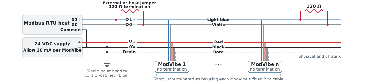
| Internal termination | None; add 120 at each trunk end |
| Protocol / format | Modbus RTU server / 8N1 |
| Nominal baud rate | 115.2k baud |
| Boosted baud rates | 230.4k or 460.8k baud |
| Firmware update | Modbus RTU bootloader |
∗ Conservative per-device bus-planning value, including the line-protection TVS diodes, RS-485 transceiver, and fixed 2 m cable [5].
Power input and protection#
ModVibe operates from 12–30 VDC between red V+ and black 0 V, with 24 VDC nominal. This range applies at the sensor after voltage drop along the power conductors. The maximum continuous input voltage is 30 VDC.
Long industrial cables can couple switching noise, EFT, and lightning-induced surges into the supply. A TVS diode with a 33.3 V minimum breakdown voltage limits these disturbances before they reach the internal electronics.
Use a 24 VDC supply with overcurrent shutdown. This limits fault energy during conductor-to-conductor shorts and wiring faults. Disconnect the supply and correct the wiring before restarting.
Fixed-cable connections#
ModVibe is supplied with a non-detachable 2 m HELUKABEL 81910 DeviceNet PUR cable. The factory-sealed cable entry forms part of the enclosure ingress protection. The bare drain provides access to the cable shield; it is not connected inside ModVibe and must not carry supply-return current. Maintain shield/drain continuity through the network. At the Modbus client or its tap, bond the shield/drain and black 0 V (Modbus Common) to protective earth (PE) at one central point only. Make no other Common-to-PE or shield-to-PE bonds on the bus [7].
Table 8. Fixed-cable conductor assignment.
| Conductor | Host connection | |
|---|---|---|
| V+ | Red | 12–30 VDC supply; 24 VDC nominal |
| 0 V | Black | Supply return and Modbus Common |
| D1+ | Blue | Modbus D1, positive line |
| D0 | White | Modbus D0, negative line |
| Drain | Bare | Cable-shield access; no internal connection |
RS-485 bus operation#
Follow Figure 11. Terminate the D1/D0 trunk with 120 at each physical end. Connect each ModVibe’s fixed 2 m cable as an unterminated stub. Validate alternative topologies for the intended cable length, node count, and baud rate. ModVibe requires no external idle bias. If another device requires polarization, use one bus-wide bias network, normally at the host.
Built-in termination
Some RS-485 host interfaces and adapters include switchable 120 termination. At a trunk end, use either the built-in termination or an external resistor, never both. Confirm that exactly one 120 termination is present at each end.
Modbus register conventions#
Register addresses in this datasheet are zero-based PDU addresses, exactly as transmitted in the Modbus request. Some PLC tools display PDU address 0 as holding register 40001; in those tools, PDU address 205 appears as 40206.
For a transparent Modbus TCP-to-RTU gateway, set the Unit Identifier in the Modbus TCP header to the assigned ModVibe unit ID[6].
R or R/O means read only; R/W means read/write; W identifies a command register whose readback is not configuration state.
Each register is one 16-bit word transmitted most-significant byte first. INT16 values use two’s complement. ModVibe UINT32 values occupy consecutive HI and LO registers, in that order.
Transfer each grouped field and UINT32 pair in one Modbus transaction; do not update or interpret individual halves separately.
Respect the block boundaries in Appendix A. Do not extend bulk reads through reserved or write-command-only addresses. Such a request returns exception 02 (ILLEGAL_DATA_ADDRESS).
Appendix A is normative for register access and exception behavior. Appendix B provides complete transactions, retry rules, and the waveform transfer procedure.
Firmware maintenance#
The integrated bootloader supports firmware updates over Modbus RTU. The update procedure and bootloader interface are controlled maintenance functions outside Revision 1 of the public register map; contact iQunet for support.
Mechanical outline and installation#
The enclosure has a rectangular body, bottom mounting boss, and side cable gland. Dimensions are nominal and exclude the cable. Use them for installation planning.
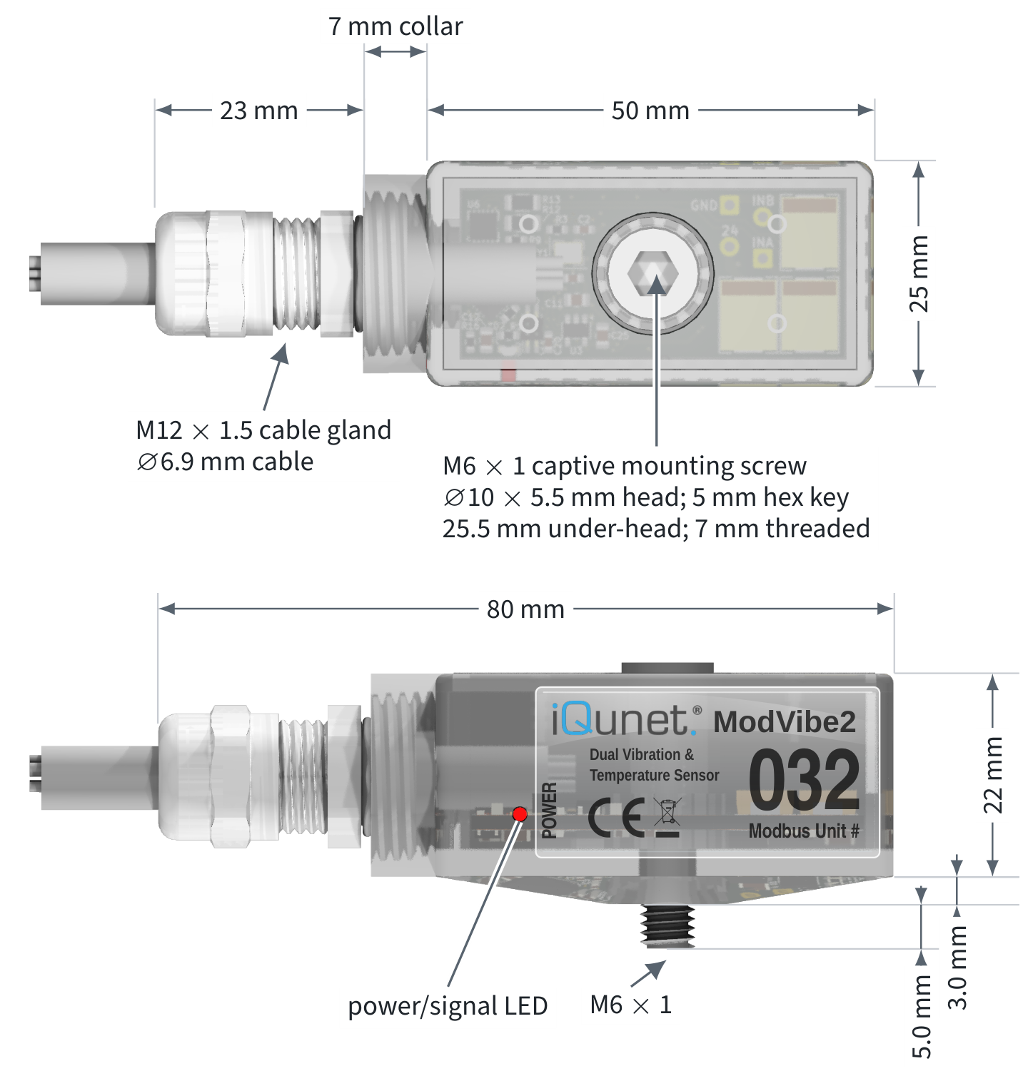
Installation dimensions#
| Feature | Specification |
|---|---|
| Body envelope (L W H) | 50 25 25 mm |
| Overall envelope incl. gland | 80 mm |
| Mounting boss | 12.6 mm; 3.0 mm projection |
| Sensor body mass | 50 g |
| Captive mounting screw | M6 1 |
| Installed screw protrusion beyond sensor mounting face | 5.0 mm |
| Installation tool | 5 mm hex key |
| Mounting torque | 1.4 Nm |
| Fixed cable type | HELUKABEL 81910 |
| Cable length / diameter | Approx. 2.0 m / 6.9 mm |
Envelope basis: H includes the 3.0 mm mounting boss. The body L W H excludes the gland, cable, screw projection, and tool clearance.
Installation principles#
The following practices support repeatable vibration measurements and consistent condition-monitoring data [8].
Select a rigid, clean, flat location that transfers machine vibration directly into the mounting boss. Do not mount on flexible covers, guards, thin plates, unsupported brackets, or other parts that can resonate independently of the machine body.
Choose one of the following rigid mounting methods:
Tapped hole: Use a centered M6 1 tapped hole with at least 5.0 mm usable thread depth. This provides the stiffest coupling.
Bonded pad: If drilling is not permitted, securely bond an M6 1 threaded mounting pad, such as the CTC MH130-6A mounting disk, to a prepared bare-metal surface, following the manufacturer’s instructions.
For either method, ensure that the mounting boss seats fully without the captive screw bottoming in the hole.
Tighten the captive mounting screw to 1.4 Nm. At the next scheduled machine inspection, check and restore the torque to 1.4 Nm to compensate for initial settling of the PA12-GF mounting interface. Keep the sensor orientation unchanged for consistent three-axis measurements.
Support the cable on the measured structure and leave a relaxed service loop near the entry. Prevent cable tension, sharp bends, and unsupported cable motion that could load the enclosure or introduce measurement artefacts.
Correct mounting affects measurement quality A vibration sensor cannot compensate for a compliant bracket, loose fastener, uneven surface, or cable-induced movement. Installation guidance and mounting torque are therefore controlled installation parameters, not informal recommendations.
Enclosure and ingress protection#
The factory-sealed ModVibe enclosure is rated IP67/IP68. The rating applies only to a complete, undamaged device with the factory cable entry intact. Do not loosen or modify the cable gland. Keep the free cable end dry or terminate it in a suitably ingress-protected enclosure.
Do not clean the device with a pressure washer. The IP rating does not establish resistance to oils, coolants, solvents, or cleaning agents.
References#
[1]
Analog Devices, ADXL380: Low Noise, Low Power, Wide Bandwidth, 3-Axis MEMS Accelerometer, Data Sheet, Rev. A, February 2026.
Open source ↗[2]
Analog Devices, ADXL382: Low Noise, Low Power, Wide Bandwidth, 3-Axis MEMS Accelerometer, Data Sheet, Rev. A, October 2025.
Open source ↗[3]
PCB Piezotronics, Model 603C01 Industrial ICP Accelerometer, Product Specification 13145, Rev. J, April 2026.
Open source ↗[4]
J. C. Robinson, Vibration Monitoring of Gearboxes, PCB Piezotronics, White Paper X1.
Open source ↗[5]
HELUKABEL, DeviceNet PUR High Flexible Thick + Thin, part no. 81910.
Open source ↗[6]
Modbus Organization, MODBUS Messaging on TCP/IP Implementation Guide, version 1.0b, October 2006.
Open source ↗[7]
Modbus Organization, MODBUS over Serial Line Specification and Implementation Guide, version 1.02, December 2006.
Open source ↗[8]
International Organization for Standardization, Condition monitoring and diagnostics of machines: Vibration condition monitoring, Part 1: General procedures, ISO 13373-1:2002, February 2002.
Open source ↗
Register map#
Find a register. See where it belongs.
No matching registers. Try a name such as TEMP_STATUS, or an address.
Capture · 200–229
Capture control and status.
Full capture referenceThis document defines the customer-accessible holding-register interface for ModVibe 2.0 application firmware. It covers device identity, temperature and health, waveform capture, paged data transfer, and an optional baud-rate boost for faster waveform downloads.
Contract-first integration This register map defines the exact application firmware 1.03 tuple: identity 2, map 3, capture 5, data window 3, and FIR catalog 3. Require APP_VERSION 0x00000103 and those contract values together. Reject mixed tuples and do not infer compatibility from a later firmware version.
Document scope#
Application-mode Modbus holding registers
Zero-based protocol addresses
Access type, data format, units, and value definitions
Capture control and paged waveform retrieval
Error and status codes
Unlisted addresses are reserved. Service, provisioning, calibration-write, bootloader access, FIR coefficients and catalog slot details, test fault-injection, and raw debug interfaces are outside this public register map. Contact iQunet for bootloader entry or unit-ID commissioning.
Addressing convention#
Register addresses in this document are PDU addresses as transmitted on the wire. Some PLC tools display holding register 0 as 40001. Configure that translation in the tool, not in the device protocol.
First integration target Implement and verify the direct-capture path before adding the baud-rate boost. Follow the quick-start sequence in the right column; advanced workflows are documented in their dedicated sections.
Public address blocks#
| Start | End | Function |
|---|---|---|
| 0 | 13 | Identity and firmware versions |
| 32 | 36 | System status and unit ID |
| 38 | 38 | Restart command (write-only) |
| 48 | 54 | Sensor temperatures |
| 55 | 63 | Temperature-calibration readback |
| 100 | 110 | Health supervision |
| 200 | 229 | Capture control and status |
| 500 | 514 | Fast-transfer status and recovery evidence |
| 520 | 526 | Fast-transfer command |
| 1000 | 1124 | Waveform data window |
| 1200 | 1200 | FIR catalog compatibility header |
Quick start: direct capture#
Connect using Modbus RTU at 115,200 bit/s, 8-N-1, and the assigned unit ID.
Read registers 0–13 and require identity contract 2, application version 0x00000103, and register-map contract 3.
Read registers 200–201 together and register 1200 separately. Require capture contract 5, data-window contract 3, and FIR catalog contract 3.
Write one complete capture configuration.
Write START to register 204 and poll
CAPTURE_STATUS(202).When READY, page through registers 1000–1124 using the explicit offset at registers 228–229.
Protocol conventions#
Serial and framing#
| Parameter | Value |
|---|---|
| Physical layer | Two-wire RS-485 |
| Normal baud rate | 115,200 bit/s |
| Character format | 8 data, no parity, 1 stop |
| Unit ID | Printed on device label |
| Valid unit-ID range | 1–247 |
| Read Holding Registers | FC03 |
| Write Single Register | FC06 |
| Write Multiple Registers | FC16 |
| Read limit | 125 registers |
| Multiple-write limit | 123 registers |
Modbus CRC-16 is transmitted low byte first. Values inside the Modbus PDU use the normal big-endian byte order.
Broadcast START at register 204 requests near-simultaneous direct captures. Modbus devices do not respond to broadcast requests, so poll each device afterward and verify status, error, and waveform ID before downloading data.
Word and integer order#
Every register is one unsigned 16-bit protocol word. Signed 16-bit values use two’s complement. A 32-bit value occupies consecutive HI and LO registers:
value = (HI << 16) | LO
Read related multiword values as one coherent block in a single FC03 (Read Holding Registers) transaction.
Access notation#
| Mark | Meaning |
|---|---|
| R | Read-only |
| R/W | Read/write |
| W | Write-only command; cannot be read back |
Unsupported function code: exception 01 (illegal function).
Unsupported address: exception 02 (illegal data address).
Invalid value: exception 03 (illegal data value), unless the relevant feature contract defines a more specific in-band error or status result.
Atomic capture configuration#
Use function 16 (Write Multiple Registers) for capture-configuration block writes and for all 32-bit register pairs. Any configuration change immediately invalidates previously ready output. Complete the capture configuration before writing START.
Modbus TCP-to-RTU and client ownership Capture configuration, waveform ID, window offset, and returned data pages form one transaction. Serialize access per device, especially through a Modbus TCP-to-RTU gateway, to prevent another client from replacing the configuration or seeking the shared window.
Retry after a timeout#
After a write timeout, safely repeat configuration and seek writes with the same values. Before repeating START, read status and waveform ID to determine whether the capture started. A repeated START clears the current output and begins a new capture.
Identity and version registers#
| Addr. | Name | Access | Format | Description |
|---|---|---|---|---|
| 0 | ID_MAGIC_HIGH |
R | u16 | Fixed 0x4649 |
| 1 | ID_MAGIC_LOW |
R | u16 | Fixed 0x5642 |
| 2 | ID_CONTRACT |
R | u16 | Identity contract; current 0x02 |
| 3 | MAP_CONTRACT |
R | u16 | Register-map contract; current 0x03 |
| 4 | HW_GENERATION |
R | u16 | Hardware generation; current 0x01 (revision A) |
| 5 | FEATURE_FLAGS |
R | bits | Identity feature flags; current 0x0000 (none) |
| 6–8 | DEVICE_ID |
R | 3 u16 | Provisioned 48-bit MAC address, high word first |
| 9–10 | APP_VERSION |
R | u32 | Application version, HI then LO |
| 11–12 | BOOT_VERSION |
R | u32 | Bootloader version, HI then LO |
| 13 | BOOT_CONTRACT |
R | u16 | Boot contract version |
ID_MAGIC: Identifies ModVibe during automatic device discovery and Modbus bus scans.ID_CONTRACT: Verify before interpreting identity registers 0–13.MAP_CONTRACT: Versions the public register map; reject unsupported values.FEATURE_FLAGS: Reserved for future identity capabilities; current firmware reports0x0000. Reject unsupported bits.
System status and restart#
| Addr. | Name | Access | Format | Description |
|---|---|---|---|---|
| 32 | RESERVED |
R | u16 | Unused; reads 0 |
| 33 | SYSTEM_STATUS |
R | enum | System-command result: 1 completed; 2 in progress; 3 failed |
| 34 | LAST_COMMAND |
R | u16 | Last system command value |
| 35 | ACTIVE_UNIT_ID |
R | u16 | Active Modbus unit ID |
| 36 | UNIT_ID_MIRROR |
R | u16 | Runtime configuration mirror |
| 37 | RESERVED |
– | – | Not readable or writable |
| 38 | RESTART_COMMAND |
W | enum | 0x5201 restarts the application |
System and capture status SYSTEM_STATUS and LAST_COMMAND report service-command results; they do not indicate device health or capture progress. Use HEALTH_STATUS (101) or CAPTURE_STATUS (202) instead.
Unit ID commissioning and block reads#
The factory-assigned Modbus unit ID is printed on the device label and lies in the range 1–247. ACTIVE_UNIT_ID (35) and UNIT_ID_MIRROR (36) are runtime values and normally match; register 36 is not persistent-storage readback. A controlled commissioning interface can change the runtime unit ID or persist a new assignment for later application starts. Contact iQunet for access.
For block reads, stop at register 36. Registers 37 and 38 are not readable and must not be included in that FC03 request.
Application restart#
Write 0x5201 to register 38 only with FC06 and never broadcast the command. The device sends the write response before restarting. The Modbus link then disappears; reconnect at 115,200 bit/s using the assigned unit ID and repeat the identity and contract checks before continuing.
Temperature#
Temperature registers (48–54)#
| Addr. | Name | A | Format | Description |
|---|---|---|---|---|
| 48 | TEMP_ADXL380 |
R | i16 | 0.1 C/count |
| 49 | TEMP_ADXL382 |
R | i16 | 0.1 C/count |
| 50 | TEMP_ADXL380_RAW |
R | i16 | Sign-extended 12-bit code |
| 51 | TEMP_ADXL382_RAW |
R | i16 | Sign-extended 12-bit code |
| 52 | TEMP_STATUS |
R | bits | Validity/calibration flags; see Section A.4.2 |
| 53 | TEMP_ADXL380_AGE |
R | u16 | Seconds since refresh |
| 54 | TEMP_ADXL382_AGE |
R | u16 | Seconds since refresh |
TEMP_ADXL380 (48) and TEMP_ADXL382 (49) report each accelerometer’s internal temperature at 0.1 C per count.
These values do not represent exact machine-surface or ambient-air temperatures. The IP67/IP68-rated enclosure and sensor packages introduce thermal delay, and internal power dissipation can add a temperature offset. See
for details.
TEMP_ADXL380_RAW (50) and TEMP_ADXL382_RAW (51) expose sign-extended, uncalibrated 12-bit temperature codes. See the Analog Devices ADXL380 data sheet and ADXL382 data sheet for encoding and conversion details.
TEMP_STATUS (52) contains the validity, freshness, and calibration flags defined in Section A.4.2.
TEMP_ADXL380_AGE (53) and TEMP_ADXL382_AGE (54) report the elapsed seconds since the corresponding reading was refreshed.
Temperature status bits (register 52)#
TEMP_STATUS (52) bit definitions, repeated for reference. ADXL380_VALID (52.0) and ADXL382_VALID (52.4) indicate that a usable temperature is stored for the corresponding sensor. Require the corresponding VALID flag before using the temperature.
ADXL380_LIVE (52.1) and ADXL382_LIVE (52.5) indicate that the latest asynchronous refresh succeeded for the corresponding sensor. LIVE alone does not guarantee a recent reading. Use TEMP_ADXL380_AGE (53) or TEMP_ADXL382_AGE (54) to apply the application’s freshness limit. If VALID is set while LIVE is clear, the snapshot contains the last usable stored value and the AGE register gives its age.
ADXL380_CAL (52.8) and ADXL382_CAL (52.9) indicate that device-specific temperature calibration was applied to the corresponding temperature value. CAL_DEFAULT (52.10) indicates that only the accelerometer’s factory trim is in use. CAL_BAD_PAGE (52.11) indicates that the stored calibration is invalid.
Temperature polling Read 48–54 as one coherent cached snapshot. A read returns immediately. A missing or stale snapshot queues one asynchronous refresh after the Modbus response; no sensor I2C occurs inline. Physical captures also request a refresh. Without temperature reads or physical captures, the cache can remain stale indefinitely. A failed refresh preserves the last VALID value and age but clears the affected LIVE bit.
Temperature-calibration readback#
| Addr. | Name | A | Format | Content |
|---|---|---|---|---|
| 55 | CAL_STATUS |
R | bits | Active calibration state |
| 56 | CAL_VERSION |
R | u16 | Current schema version 0x01 |
| 57–58 | CAL_GENERATION |
R | u32 | Commit count, HI/LO |
| 59 | ADXL380_OFFSET |
R | i16 | Offset, 0.1 C/count |
| 60 | ADXL382_OFFSET |
R | i16 | Offset, 0.1 C/count |
| 61 | CAL_REFERENCE |
R | i16 | Reference, 0.1 C/count |
| 62 | ADXL380_CAL_RAW |
R | i16 | Raw code at calibration |
| 63 | ADXL382_CAL_RAW |
R | i16 | Raw code at calibration |
CAL_STATUS (55) summarizes the active calibration record. Its flags show whether the record is valid, which sensor corrections are applied, whether factory defaults are in use, and whether an invalid stored page was detected.
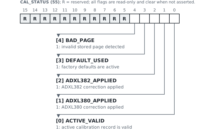
CAL_STATUS (55) bit definitions. CAL_VERSION (56) identifies the format of the active calibration record. The current schema is 0x01; the register is zero when no valid stored record is active.
CAL_GENERATION (57–58) is a 32-bit counter, high word first. It increments after each successful calibration commit. Firmware stores two redundant calibration pages and uses this counter to select the newest valid record at startup.
ADXL380_OFFSET (59) and ADXL382_OFFSET (60) contain signed corrections. Under schema 0x01, firmware first converts the raw sensor code to an uncalibrated temperature and then applies the corresponding offset:
is
TEMP_ADXL380(48) orTEMP_ADXL382(49).is obtained by converting the corresponding
TEMP_ADXL380_RAW(50) orTEMP_ADXL382_RAW(51) value as specified in its ADXL data sheet.is
ADXL380_OFFSET(59) orADXL382_OFFSET(60).
All three formula terms use 0.1 C units.
CAL_REFERENCE (61) records the reference temperature used for the calibration. ADXL380_CAL_RAW (62) and ADXL382_CAL_RAW (63) record the corresponding sign-extended raw sensor codes captured at that calibration point.
Health#
Registers 100–110 expose one coherent health-supervisor snapshot. The “live” fields describe the latest completed supervisor cycle; retained fields preserve the most recent failed check and the firmware response.
Health diagnostics identify inconsistent internal firmware state. They are not a comprehensive hardware self-test. They do not report the outcome of a specific capture. Use each feature’s own status and error registers for that purpose.
Health registers (100–110)#
| Addr. | Name | A | Format | Description |
|---|---|---|---|---|
| 100 | HEALTH_CONTRACT |
R | u16 | This contract: 0x01 |
| 101 | HEALTH_STATUS |
R | enum | Latest cycle: 0 OK; 1 FAULT |
| 102–103 | RUN_COUNT |
R | u32 | Supervisor cycles, HI/LO |
| 104–105 | FAULT_COUNT |
R | u32 | Failed checks, HI/LO |
| 106 | FAULT_BITS |
R | bits | Latest-cycle fault mask |
| 107 | LAST_OWNER |
R | enum | Service subsystem code |
| 108 | LAST_VALIDATOR |
R | enum | Service check code |
| 109 | LAST_ACTION |
R | enum | Retained response |
| 110 | LAST_FAULT_BITS |
R | bits | Retained fault mask |
HEALTH_CONTRACT (100) versions the layout and semantics of registers 101–110. Require 0x01 before interpreting the remaining fields.
The supervisor runs every 100 ms. It checks the protected states used for Modbus communication, capture, and fast transfer. Depending on the failed check, firmware takes one of three actions:
repairs the state;
stops the affected operation in a safe error state; or
records the fault condition without changing the state.
Current status and counters#
HEALTH_STATUS (101) reports whether the latest supervisor cycle found a fault. FAULT_BITS (106) identifies every subsystem that failed in that cycle. Both are recalculated each cycle and clear after a healthy cycle.
HEALTH_STATUS (101), FAULT_BITS (106), and firmware responses, repeated for reference. RUN_COUNT (102–103) is a 32-bit counter, high word first, that increments once per completed supervisor cycle. A change between reads confirms that supervision is running.
FAULT_COUNT (104–105) is a 32-bit counter, high word first, that increments once for each failed check. A persistent fault can add one count every 100 ms, and several failed checks can add several counts in one cycle. Within one application run, a counter increase reveals intermittent faults that cleared before polling.
Fault diagnosis and recovery#
When a check fails, firmware updates registers 107–110 as one retained record. Healthy cycles leave this record unchanged. If several checks fail during one cycle, it describes the last check processed. A nonzero retained value therefore does not by itself indicate an active fault. The health block is volatile and cleared on every application start, including a commanded restart, watchdog recovery, or power cycle. Save the snapshot first.
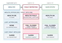
LAST_FAULT_BITS (110) identifies the most recently retained fault using the same bit definitions as FAULT_BITS (106) and selects the corresponding table row. LAST_ACTION (109) records the firmware response; verify that it matches the listed response.
Apply the listed next step only when diagnosing a newly observed fault. An older retained record does not require the recovery action to be repeated.
| Fault mask | Area | Response (109) | Next step |
|---|---|---|---|
0x0000 |
None | 0, NONE |
No retained fault |
0x0001 |
Reserved | N/A | N/A |
0x0002 |
Modbus RTU | 3, REPAIR |
Verify SYSTEM_STATUS (33) is valid and mirrors 35–36 match the assigned ID |
0x0004 |
Waveform capture | 2, FAIL_CLOSED |
Discard result; reconfigure and retry |
0x0008 |
Reserved | N/A | N/A |
0x0010 |
Fast transfer | 1, REPORT_ONLY |
Stop requests; follow Section A.10.2 |
Implementation workflow.
On connection, read 100–110 in one FC03 transaction and require
HEALTH_CONTRACT=0x0001. Store the snapshot as the baseline. A retained fault is historical unless its live bit is set.Within one application run, use
HEALTH_STATUSandFAULT_BITSfor active faults. A changedFAULT_COUNTproves that at least one check failed since the previous poll; it is not an event count.For each set
FAULT_BITSbit, use the table to identify the area. If the live mask is clear,LAST_FAULT_BITSidentifies the most recent area. For detail, read 33–36 (Modbus RTU), 200–229 (capture), or 500–514 (fast transfer).Use feature-specific status and error registers to determine success and retry. A cleared health bit confirms only internal consistency.
LAST_OWNER (107) and LAST_VALIDATOR (108) are opaque service-diagnostic codes.
Configure a waveform capture#
Use Sections 1 and 2 of the main datasheet to choose the sensor, range, output rate, and record length. The tables below show how to encode those choices in the capture request. Section A.7 explains how to start and monitor the request; Section A.8 explains how waveform data is paged for Modbus download.
All capture-block addresses from 200 through 229 are readable. Only fields marked R/W are writable. Registers 205–213 form the capture request, and register 204 is the command register.
Contracts and capture request#
Require CAPTURE_CONTRACT=0x0005 before interpreting registers 202–227.
Section 1.6 explains the waveform configuration.
| Addr. | Name | A | Format | Description |
|---|---|---|---|---|
| 200 | CAPTURE_CONTRACT |
R | u16 | Require 0x0005 |
| 201 | WINDOW_CONTRACT |
R | u16 | Require 0x0003 |
| 202 | CAPTURE_STATUS |
R | enum | Lifecycle; see Section A.7 |
| 203 | ERROR |
R | enum | Result/error; see Section A.7 |
| 204 | CONTROL |
R/W | enum | 0 IDLE; 1 START |
| 205 | SOURCE |
R/W | enum | 2 ADXL380; 3 ADXL382 |
| 206 | CHANNEL_MASK |
R/W | bits | Require 0x0007: X/Y/Z |
| 207 | OUTPUT_RATE_HZ |
R/W | u16 | Per-axis values: ADXL380: 125, 250, 500, 1000, 2000, 4000, 8000 S/s; ADXL382: 125, 250, 500, 1000, 2000, 4000, 8000, 16000 S/s |
| 208–209 | SAMPLES_PER_CHANNEL |
R/W | u32 | HI/LO; 64, 128, 256, 512, 1024, 2048, 4096, or 8192 |
| 210 | FILTER_PROFILE |
R/W | enum | Require 0x0003 |
| 211 | DOWNLOAD_POLICY |
R/W | enum | Require 1 |
| 212 | MAX_DOWNLOAD_MS |
R/W | u16 | Require 30000 ms |
| 213 | FULL_SCALE_G |
R/W | u16 | ADXL380: 4, 8, or 16 g; ADXL382: 15, 30, or 60 g |
Filter profile 3 applies FIR decimation at reduced rates and full-rate bypass at 8 kS/s for ADXL380 or 16 kS/s for ADXL382.
Result, capability, and paging registers#
Require WINDOW_CONTRACT=0x0003 before using registers 228–229 or the waveform-data window.
| Addr. | Name | A | Format | Description |
|---|---|---|---|---|
| 214–215 | OUTPUT_WORDS |
R | u32 | 3 samples/axis |
| 216–217 | CHUNK_COUNT |
R | u32 | |
| 218–219 | EST_DOWNLOAD_MS |
R | u32 | Paging estimate at 115,200 bit/s |
| 220 | WAVEFORM_ID |
R | u16 | Nonzero ID when READY |
| 221–222 | MAX_OUTPUT_WORDS |
R | u32 | Buffer capacity |
| 223 | CHUNK_PAYLOAD_WORDS |
R | u16 | = 122 payload words/page |
| 224 | CHUNK_HEADER_WORDS |
R | u16 | = 3 header words/page |
| 225 | SUPPORTED_SOURCE_MASK |
R | bits | Bits 1/2: ADXL380/ADXL382; = 0x0006 |
| 226 | SUPPORTED_CHANNEL_MASK |
R | bits | Bits 0/1/2: X/Y/Z; = 0x0007 |
| 227 | NORMAL_MAX_DOWNLOAD_MS |
R | u16 | Maximum download budget: 30,000 ms |
| 228–229 | WINDOW_OFFSET |
R/W | u32 | Payload offset; see Section A.8 |
Use registers 214–220 only while status is READY. Read them together before paging. Capability registers 221–227 do not expand the released combinations in Section A.6.1. MAX_OUTPUT_WORDS is buffer capacity, not an accepted request size; the largest released request is 24,576 words (3 axes 8,192 samples/axis).
Write, run, and monitor a capture#
Refer to Section 2.1 for the complete capture and polling workflow.
Write the configuration#
Write registers 205–213 together with FC16 (Write Multiple Registers) to store one complete capture configuration. START validates the configuration and its transfer budget before acquisition begins.
Configuration writes invalidate READY output Any write to 205–213 stops the current request, invalidates a READY waveform, clears its metadata, sets WAVEFORM_ID (220) to 0x0000, and sets status to CONFIGURED. Complete an active download before rewriting the request.
Status and control values#
| Value | Name | Meaning |
|---|---|---|
CAPTURE_STATUS (202) enum |
||
| 0 | IDLE | No active request |
| 1 | CONFIGURED | Stored; not started |
| 2 | ACQUIRING | Acquiring samples into SRAM |
| 3 | PROCESSING | Processing captured samples |
| 4 | READY | Output is valid |
| 5 | ERROR | Read ERROR (203) |
CONTROL (204) enum |
||
| 0 | IDLE | Cancel; clear output, error, and ID |
| 1 | START | Validate and begin acquisition |
Values from 6 through 65535 are not valid CAPTURE_STATUS values. An aborted capture reports status ERROR (5) with ERROR (203) set to ABORTED (12). A client must treat any status value above 5 as an incompatible firmware state.
Start, poll, and retry#
Before START. Read 202–220 together. Require status (202) = CONFIGURED, error (203) = NONE, waveform ID (220) = 0x0000, and request block 205–213 to match the requested configuration.
Normal polling. Write START=1 to CONTROL (204) with FC06. After the expected record duration, read 202–203 with FC03 at one-second intervals. Status 2 or 3 with error NONE means capture is in progress. On READY, read 202–220 together; require status READY, error NONE, and a nonzero ID in that snapshot. IDs range from 0x1 to 0xffff and wrap to 0x1. ERROR is terminal; other combinations restart the identity and configuration sequence.
Unconfirmed START. After configuring several devices, broadcast START to request near-simultaneous captures on one RS-485 bus. Broadcast requests have no response, so poll 202–220 together on each device at the normal interval. Apply the normal outcomes above, except that a device remaining CONFIGURED with error NONE, ID 0x0000, and matching 205–213 did not receive a valid broadcast START; retry START once by unicast.
Capture error values (register 203)#
| Value | Name | Meaning |
|---|---|---|
| 0 | NONE | No capture error |
| 1 | BAD_CONFIG | Invalid field or combination |
| 2 | UNSUPPORTED_SOURCE | Source not available |
| 3 | UNSUPPORTED_CHANNEL_MASK | Requested channel mask unsupported |
| 4 | UNSUPPORTED_RATE | Output rate not available |
| 5 | UNSUPPORTED_FILTER | Filter profile not available |
| 6 | OUTPUT_TOO_LARGE | Output exceeds device capacity |
| 7 | DOWNLOAD_BUDGET_EXCEEDED | Transfer exceeds policy |
| 8 | SENSOR_NOT_READY | Source cannot start |
| 9 | SENSOR_FAULT | Source reported a fault |
| 10 | PROCESS_OVERRUN | Processing did not keep pace |
| 11 | BUFFER_BUSY | Required buffer is unavailable |
| 12 | ABORTED | Capture aborted |
| 13 | INTERNAL_ERROR | Fail-closed internal error |
Paged waveform data window#
The data block at addresses 1000–1124 is always 125 registers: a three-word header followed by 122 signed payload words. The host selects a payload offset by writing the 32-bit WINDOW_OFFSET at 228–229, then reads all 125 data registers in one function-03 transaction.
| Data address | Access | Format | Description |
|---|---|---|---|
| 1000 | R | u16 | Waveform ID |
| 1001 | R | u16 | Offset high word |
| 1002 | R | u16 | Offset low word |
| 1003–1124 | R | i16 | Payload; zero-padded at end |
Random-access seek rules#
Offset 0 is always permitted.
A nonzero offset must be less than
OUTPUT_WORDS.A nonzero offset must be a multiple of 122 words.
Write both offset words together with function 16.
Reading a page does not auto-advance the offset.
Because reads do not mutate cursor state, the same page can be read again after a timeout or CRC failure. The returned header proves which waveform ID and offset the payload belongs to.
Payload layout#
Vibration samples are signed 16-bit acceleration counts. Each X, Y, and Z block contains consecutive time samples. The three blocks appear in this order:
X0 ... X(N-1), Y0 ... Y(N-1), Z0 ... Z(N-1)
Nominal waveform scaling#
SOURCE (205) |
FULL_SCALE_G (213) |
Nominal LSB/g |
|---|---|---|
| 2 (ADXL380) | 4 ( g) | 7500 |
| 2 (ADXL380) | 8 ( g) | 3750 |
| 2 (ADXL380) | 16 ( g) | 1875 |
| 3 (ADXL382) | 15 ( g) | 2000 |
| 3 (ADXL382) | 30 ( g) | 1000 |
| 3 (ADXL382) | 60 ( g) | 500 |
Convert waveform words from payload registers 1003–1124 to signed 16-bit two’s-complement values. Divide each value by the applicable nominal LSB/g to obtain acceleration in g. This scale comes from the sensor data sheets; it is not a shaker-certified amplitude calibration.
Minimal page loop#
Save
WAVEFORM_ID(220) andOUTPUT_WORDS(214–215).Set
WINDOW_OFFSET(228–229) to 0 with FC16.Read 125 registers from address 1000 with FC03.
Verify header: waveform ID (1000) and offset (1001–1002).
Append payload 1003–1124; stop at saved
OUTPUT_WORDS.If data remains, increment
WINDOW_OFFSET(228–229) by 122 with FC16; repeat step 3.
Retry safety On a timeout or CRC error, retry the same seek and page read. Never append a page unless its header matches the expected waveform ID and offset. This prevents stale, duplicated, or reordered data from entering a waveform.
FIR catalog compatibility header#
Register 1200, FIR_CATALOG, is a read-only u16 compatibility header. Application firmware 1.03 reports 0x0003. Clients shall use it only as part of the exact release tuple; FIR coefficient and catalog slot details are not part of this public interface.
Baud-rate boost#
Fast transfer changes one ModVibe from 115,200 bit/s to 230,400 or 460,800 bit/s and requires exclusive ownership of the RTU bus until that device returns to 115,200 bit/s. These optional rates are ModVibe-specific, not standard Modbus defaults. Clients must implement the rate-change and recovery procedure before selecting them.
The lease is the maximum permitted interval between valid requests handled by the selected ModVibe while FAST_ACTIVE. Each request restarts the timer; traffic to another device does not. The lease limits the gap between requests, not the total session duration. Clients without boost remain fully compatible at 115,200 bit/s.
Fast-transfer status block (500–514)#
Read registers 500–514 together with FC03 as one status snapshot.
| Addr. | Name | A | Format | Description |
|---|---|---|---|---|
| 500 | FAST_CONTRACT |
R | u16 | Current 0x0002 |
| 501 | FAST_STATUS |
R | enum | Current lifecycle |
| 502 | FAST_ERROR |
R | enum | Error/fallback cause |
| 503 | SUPPORTED_BAUD_MASK |
R | bits | Supported rate codes |
| 504 | DEFAULT_BAUD_CODE |
R | enum | Nominal rate code |
| 505 | ACTIVE_BAUD_CODE |
R | enum | Current rate code |
| 506 | MAX_LEASE_MS |
R | u16 | Maximum request gap |
| 507 | GUARD_MS |
R | u16 | Minimum switch guard |
| 508 | CONFIRM_TIMEOUT_MS |
R | u16 | Confirmation deadline |
| 509–510 | ACTIVE_NONCE |
R | u32 | Current session nonce |
| 511 | SESSION_COUNTER |
R | u16 | Accepted sessions |
| 512 | FALLBACK_COUNTER |
R | u16 | Fallback attempts |
| 513 | RECOVERY_ACTION |
R | enum | Retained recovery action |
| 514 | RECOVERY_ERROR |
R | enum | Retained recovery cause |
Contract and state. FAST_CONTRACT (500) versions the block; require 0x0002. FAST_STATUS (501) is the authoritative session state and is interpreted together with FAST_ERROR (502).
| Value | FAST_STATUS (501) |
Meaning |
|---|---|---|
| 0 | IDLE | Link uses the default rate |
| 1 | SWITCH_PENDING | Rate switch scheduled |
| 2 | FAST_PENDING_CONFIRM | Awaiting confirmation |
| 3 | FAST_ACTIVE | Boost lease is active |
| 4 | REVERT_PENDING | Return scheduled |
| 5 | FAILED | Internal rate-change failure |
FAST_ERROR (502) gives the cause of a rejected command or automatic fallback and can remain nonzero after status returns to IDLE.
Table 9. FAST_ERROR (502) values.
| Value | FAST_ERROR (502) |
Meaning |
|---|---|---|
| 0 | NONE | No fast-transfer error |
| 1 | UNSUPPORTED_BAUD | Select an advertised code |
| 2 | BUSY | Reread status before retrying |
| 3 | BAD_NONCE | New nonce for START; active nonce thereafter |
| 4 | LEASE_ERROR | Correct lease, or recover after expiry |
| 5 | NOT_EXCLUSIVE | Do not use boost on this link |
| 6 | CONFIRM_TIMEOUT | Reconnect after the recovery wait |
| 7 | INTERNAL | Stop boost requests and recover |
SUPPORTED_BAUD_MASK (503) advertises the boost codes accepted by START_TEMPORARY; firmware 1.03 reports 0x0006. DEFAULT_BAUD_CODE (504) is 0 for the nominal 115,200 bit/s rate and is not part of the boost mask.
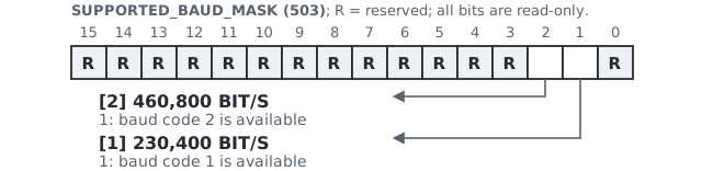
Boost session, timing, and counters (505–512)#
ACTIVE_BAUD_CODE (505) reports the current link rate using the enum below.
| Code | Rate |
|---|---|
| 0 | 115,200 bit/s |
| 1 | 230,400 bit/s |
| 2 | 460,800 bit/s |
Timing fields. Registers 506–508 use milliseconds.
MAX_LEASE_MS (506) is the longest permitted interval between valid Modbus requests during a boosted session; firmware 1.03 reports 5,000 ms. Firmware 1.03 accepts LEASE_MS values from 1,000 ms through this limit.
GUARD_MS (507) is the minimum silence after the complete START or REVERT response. Change the host UART, then wait this interval plus its switching margin before transmitting at the new rate.
CONFIRM_TIMEOUT_MS (508) is the confirmation deadline. It starts when the device accepts START_TEMPORARY. Before it expires, the device must accept CONFIRM_FAST at the boosted rate. Firmware 1.03 reports 250 ms. On expiry, the device returns to 115,200 bit/s.
Session. ACTIVE_NONCE (509–510) reports the client-selected nonce from START_TEMPORARY. Reuse it in CONFIRM_FAST and REVERT. It remains available until IDLE, then reads zero.
Counters. SESSION_COUNTER (511) counts accepted boost sessions. FALLBACK_COUNTER (512) counts automatic fallback attempts after a missing confirmation or lease expiry. Both are volatile: they wrap from 0xFFFF to 0x0000 and clear at application start. Command value 4 (CLEAR_RECOVERY) does not change them.
Baud-rate recovery record (513–514)#
RECOVERY_ACTION (513) identifies the recovery method.
| Value | RECOVERY_ACTION (513) |
Meaning |
|---|---|---|
| 0 | NONE | No abnormal recovery retained |
| 4 | RESTORE_NOMINAL_BAUD | Baud rate restored; no reset |
| 5 | SOFTWARE_RESET_RECOVERY | Application reset restored 115,200 bit/s |
RECOVERY_ERROR (514) uses the enum in Table 9. Explicit REVERT creates no retained recovery record.
A later abnormal recovery atomically replaces both fields. They survive software and watchdog resets until CLEAR_RECOVERY is issued or power is lost.
Baud-rate command block and values (520–526)#
Write all seven write-only registers together with FC16. COMMAND_MAGIC and FLAGS have fixed values; each command defines the remaining field constraints.
| Addr. | Name | A | Format | Value/role |
|---|---|---|---|---|
| 520 | COMMAND_MAGIC |
W | u16 | Intent marker: 0xF157 |
| 521–522 | COMMAND_NONCE |
W | u32 | Client session token |
| 523 | BAUD_CODE |
W | enum | Rate code; see A.9.2 |
| 524 | LEASE_MS |
W | u16 | Requested gap limit, ms |
| 525 | FLAGS |
W | bits | Reserved; require 0 |
| 526 | COMMAND |
W | enum | Operation code below |
| Value | COMMAND (526) |
Required fields |
|---|---|---|
| 1 | START_TEMPORARY | New nonzero nonce; BAUD_CODE 1 or 2; LEASE_MS: 1,000 to MAX_LEASE_MS |
| 2 | CONFIRM_FAST | Active nonce from START_TEMPORARY; BAUD_CODE and LEASE_MS both 0 |
| 3 | REVERT | Active nonce from START_TEMPORARY; BAUD_CODE and LEASE_MS both 0 |
| 4 | CLEAR_RECOVERY | Nonce, BAUD_CODE, and LEASE_MS all 0 |
Use and recover the baud-rate boost#
Boost and return sequence#
Use the Section A.9.4 command fields. Boost only a READY waveform: complete the capture and save WAVEFORM_ID (220) first. Otherwise, capture time can consume the lease before downloading begins.
At 115,200 bit/s, read 500–514. Require contract version 2 and target-rate support; otherwise do not use boost. Require status IDLE, active baud code 0, nonce 0, and
RECOVERY_ACTION(513) = 0. If communication or any state or record check fails, follow Section A.10.2. Save 506–508.Send START_TEMPORARY (1) at 115,200 bit/s with a new nonce and normally a 1,000 ms lease. Increase the lease only for a longer expected request gap plus transfer and scheduling margin; do not exceed
MAX_LEASE_MS(506). After the complete response, switch to the target rate, then waitGUARD_MS(507) plus the host switching margin before transmitting.At the target rate, send CONFIRM_FAST with the same nonce. Require
FAST_STATUS(501) = FAST_ACTIVE,FAST_ERROR(502) = NONE, the target code inACTIVE_BAUD_CODE(505), and the nonce inACTIVE_NONCE(509–510).Download the READY waveform. Keep the interval between valid Modbus transactions shorter than the requested lease.
At the target rate, send REVERT with the same nonce and receive the complete response. Set the host to 115,200 bit/s, then wait
GUARD_MS(507) plus the host switching margin. Read 500–514 together and requireFAST_STATUS(501) = IDLE,FAST_ERROR(502) = NONE, and bothACTIVE_BAUD_CODE(505) andACTIVE_NONCE(509–510) = 0.
REVERT is also accepted from FAST_PENDING_CONFIRM to cancel the boost before confirmation.
Recovery after an uncertain rate change#
If one coherent FC03 read of 500–514 at 115,200 bit/s already shows contract version 2, status IDLE, active baud code 0, and nonce 0, communication is restored; continue at Retained record.
Recover communication
Stop traffic. Stop Modbus requests, set the host UART to 115,200 bit/s, and do not scan rates or transmit during the wait.
Wait. From when traffic stopped, wait at least 5,100 ms. For firmware 1.03, this covers the latest normal fallback deadline plus
GUARD_MS(507).Reconnect. At 115,200 bit/s, retry coherent FC03 reads of 500–514 for at least 5,000 ms. Require one snapshot with contract version 2, status IDLE, active baud code 0, and nonce 0. Otherwise stop and report recovery failure.
Retained record
Interpret the outcome. Read
RECOVERY_ACTION(513):NONE (0): no abnormal recovery record;
RESTORE_NOMINAL_BAUD (4): nominal rate restored without reset;
SOFTWARE_RESET_RECOVERY (5): application reset restored the nominal rate.
With NONE,
FAST_ERROR(502) may still identify a routine confirmation timeout or lease expiry. Log it andFALLBACK_COUNTER(512) if useful; do not clear. For either abnormal action, first save 100–110 and 500–514. The cause is inRECOVERY_ERROR(514).Clear abnormal evidence. For either abnormal action, send
CLEAR_RECOVERYat 115,200 bit/s while IDLE with the fields defined in Section A.9.4. It is retry-safe and clears only the retained record. RereadRECOVERY_ACTION(513) andRECOVERY_ERROR(514); require NONE in both.
Application note#
This application note performs one complete triaxial capture from the ModVibe 2.0 precision sensor. The example returns 1,024 samples per axis at 1 kS/s and converts the signed waveform words to acceleration in g.
Example result Sensor: ADXL380 precision sensor
Axes: X, Y, Z
Range: g
Output rate: 1,000 samples/s per axis
Returned duration: 1.024 s
Output: 3,072 signed words
What the host must provide#
FTDI-based USB-to-RS-485 converter
Modbus RTU functions 03, 06, and 16
Read and write access to zero-based holding-register addresses
A receive buffer for 125 registers per data page
The complete transaction#
Connect. Use 115,200 bit/s, 8-N-1, and the ModVibe unit ID shown on the device label.
Identify. Verify the device identity and capture contracts.
Configure. Write the nine-word capture request at address 205 with FC16.
Start. Write START=1 to
CONTROL(204) with FC06.Monitor. Poll
CAPTURE_STATUS(202) andERROR(203) until READY or ERROR.Read metadata. Read
WAVEFORM_ID(220) andOUTPUT_WORDS(214–215).Download. Seek and read fixed 125-register waveform pages.
Validate. Verify every page header before appending its payload.
Separate axes. Split the output into 1,024 X, 1,024 Y, and 1,024 Z samples.
Scale. Divide the signed g samples by 3,750 LSB/g.
Waveform duration excludes transfer time The returned sample duration is 1,024 / 1,000 = 1.024 s. Communication time is additional and depends on baud rate, page count, host latency, and retries.
Related document#
The ModVibe 2.0 Register Map defines every register, state, error, scale, and optional baud-rate-boost command. The example in Section B.5 does not use baud-rate boost.
Connection and protocol setup#
Power and RS-485 connections#
Connect the fixed cable as follows:
| Color | Signal | Host connection |
|---|---|---|
| Red | V+ | 12–30 VDC supply; 24 VDC nominal |
| Black | 0 V | Supply return and Modbus Common |
| Blue | D1+ | Modbus positive line |
| White | D0 | Modbus negative line |
| Bare | Drain | Cable-shield access |
The bare drain has no internal connection and must not carry return current. Follow
for shield bonding and bus-topology guidance.
Modbus operations and response checks#
| FC | Operation | Used for |
|---|---|---|
| 03 | Read holding registers | Status, metadata, data page |
| 06 | Write single register | START command |
| 16 | Write multiple registers | Config and 32-bit seek |
Before using a response, require a valid CRC and verify that it matches the outstanding request:
FC03: unit ID, function code, and expected byte count;
FC06: unit ID, function code, register address, and written value;
FC16: unit ID, function code, start address, and register count.
A function code with bit 7 set is an exception response. Stop and report its exception code. Ignore unrelated or malformed frames. If this example times out, report the failed operation and stop.
Identity check#
Read registers 0–13 as one identity block and require the common identity fields:
| Addr. | Register | Required |
|---|---|---|
| 0 | ID_MAGIC_HIGH |
0x4649 |
| 1 | ID_MAGIC_LOW |
0x5642 |
| 2 | ID_CONTRACT |
0x0002 |
Read registers 200–201 together and register 1200 separately. Accept only one complete release tuple from the following table:
| Addr. | Register | Firmware 1.02 | Firmware 1.03 |
|---|---|---|---|
| 9–10 | APP_VERSION |
0x00000102 |
0x00000103 |
| 3 | MAP_CONTRACT |
0x0002 |
0x0003 |
| 200 | CAPTURE_CONTRACT |
0x0004 |
0x0005 |
| 201 | WINDOW_CONTRACT |
0x0003 |
0x0003 |
| 1200 | FIR_CATALOG |
0x0002 |
0x0003 |
Stop with a clear compatibility error for a mixed tuple or any unknown value. This prevents a client from interpreting one contract with another release’s register semantics.
The fixed example uses ADXL380 at 1 kS/s and is supported by both tuples. Firmware 1.02 does not support reduced-rate ADXL382 capture; use the exact firmware 1.03 tuple for that path.
Address notation This note uses the zero-based address transmitted in the Modbus PDU. A PLC package may display address 0 as holding register 40001. Apply that offset once in the PLC configuration; do not add it to wire-level requests.
Known-good capture configuration#
Registers 205–213 form one coherent capture request. This example selects the ADXL380, all three axes, 1 kS/s per axis, 1,024 samples per axis, FIR decimation, and a g range. Write the complete nine-register block in one FC16 transaction.
| Addr. | Field | Value | Meaning |
|---|---|---|---|
| 205 | SOURCE |
2 | ADXL380 precision sensor |
| 206 | CHANNEL_MASK |
0x0007 |
X, Y, Z |
| 207 | OUTPUT_RATE_HZ |
1,000 | 1 kS/s per axis |
| 208 | SAMPLE_COUNT_HI |
0 | 32-bit high word |
| 209 | SAMPLE_COUNT_LO |
1,024 | 1,024 samples/axis |
| 210 | FILTER_PROFILE |
3 | FIR decimation |
| 211 | DOWNLOAD_POLICY |
1 | Enforce transfer-time budget |
| 212 | MAX_DOWNLOAD_MS |
30,000 | 30,000 ms budget |
| 213 | FULL_SCALE_G |
8 | g |
Example configuration request (FC16)
| TX bytes | Addr. | Meaning |
|---|---|---|
| 1C | Unit ID 28 | |
| 10 | FC16, write multiple holding registers | |
| 00 CD | Start at register 205 | |
| 00 09 | Write 9 registers | |
| 12 | 18 data bytes follow; CRC excluded | |
| 00 02 | 205 | SOURCE = 2, ADXL380 |
| 00 07 | 206 | CHANNEL_MASK = 0x0007, X/Y/Z |
| 03 E8 | 207 | OUTPUT_RATE_HZ = 1,000 |
| 00 00 | 208 | SAMPLE_COUNT_HI = 0 |
| 04 00 | 209 | SAMPLE_COUNT_LO = 1,024 |
| 00 03 | 210 | FILTER_PROFILE = 3 |
| 00 01 | 211 | DOWNLOAD_POLICY = 1 |
| 75 30 | 212 | MAX_DOWNLOAD_MS = 30,000 |
| 00 08 | 213 | FULL_SCALE_G = 8 |
| 71 32 | Request CRC, low byte first |
Example response
| RX bytes | Meaning |
|---|---|
| 1C | Unit ID 28 |
| 10 | FC16 response |
| 00 CD | Start register 205 accepted |
| 00 09 | 9 registers written |
| 92 7D | Response CRC, low byte first |
Frames are examples, not constants Recalculate CRC after changing unit ID, address, length, or data. A normal Modbus library constructs these frames and validates responses for you.
Example START and status poll#
After the configuration response, read registers 202–220 together and require CONFIGURED, NONE, the requested values at 205–213, and waveform ID zero. Then send START once and poll registers 202–203 together. The decoded frames below show READY with no error for unit ID 28.
See Sections A.7.2 and A.7.3 for all states and production retry rules.
Example START request (FC06)
| TX bytes | Addr. | Meaning |
|---|---|---|
| 1C | Unit ID 28 | |
| 06 | FC06, write single holding register | |
| 00 CC | 204 | CONTROL |
| 00 01 | START = 1 | |
| 8B B8 | CRC, low byte first |
Example START response (FC06)
| RX bytes | Addr. | Meaning |
|---|---|---|
| 1C | Unit ID 28 | |
| 06 | FC06 response | |
| 00 CC | 204 | CONTROL accepted |
| 00 01 | START = 1 accepted | |
| 8B B8 | CRC, low byte first |
Example status poll (FC03)
| TX bytes | Addr. | Meaning |
|---|---|---|
| 1C | Unit ID 28 | |
| 03 | FC03, read holding registers | |
| 00 CA | 202 | Start at CAPTURE_STATUS |
| 00 02 | Read 2 registers | |
| E7 B8 | Request CRC, low byte first |
Repeat this poll every few seconds until CAPTURE_STATUS reports READY or ERROR.
Valid status values are 0 through 5. An aborted capture reports ERROR (5) with ERROR set to ABORTED (12). Treat any status value above 5 as an incompatible firmware state.
Example READY response (FC03)
| RX bytes | Addr. | READY/NONE meaning |
|---|---|---|
| 1C | Unit ID 28 | |
| 03 | FC03 response | |
| 04 | 4 data bytes follow; CRC excluded | |
| 00 04 | 202 | CAPTURE_STATUS = READY |
| 00 00 | 203 | ERROR = NONE |
| 76 F3 | Response CRC, low byte first |
Validate and download the example#
After READY, read registers 202–224 together and use:
| Addr. | Field | Check / role |
|---|---|---|
| 202 | CAPTURE_STATUS |
READY |
| 203 | ERROR |
NONE |
| 204–213 | Require 205–213 to match at READY and before download | |
| 214–215 | OUTPUT_WORDS |
3,072 |
| 216–217 | CHUNK_COUNT |
26 |
| 218–219 | EST_DOWNLOAD_MS |
Informational |
| 220 | WAVEFORM_ID |
Nonzero |
| 221–222 | MAX_OUTPUT_WORDS |
At least 3,072 |
| 223 | CHUNK_PAYLOAD_WORDS |
122 |
| 224 | CHUNK_HEADER_WORDS |
3 |
Use the reported values for paging. This request returns 3,072 signed payload words.
Example page seek (FC16)
| TX bytes | Addr. | Meaning |
|---|---|---|
| 1C | Unit ID 28 | |
| 10 | FC16, write multiple holding registers | |
| 00 E4 | 228 | Start at WINDOW_OFFSET |
| 00 02 | Write 2 registers | |
| 04 | 4 data bytes follow; CRC excluded | |
| 00 00 | 228 | Offset high word = 0 |
| 00 00 | 229 | Offset low word = 0 |
| 93 78 | Request CRC, low byte first |
Example page read (FC03)
| TX bytes | Addr. | Meaning |
|---|---|---|
| 1C | Unit ID 28 | |
| 03 | FC03, read holding registers | |
| 03 E8 | 1000 | Start of waveform-data page |
| 00 7D | Read 125 registers | |
| 06 16 | Request CRC, low byte first |
Page response layout at offset 0
| RX bytes | Addr. | Meaning |
|---|---|---|
| 1C | Unit ID 28 | |
| 03 | FC03 response | |
| FA | 250 data bytes follow; CRC excluded | |
| xx xx | 1000 | Current waveform ID |
| 00 00 | 1001 | Returned offset high word = 0 |
| 00 00 | 1002 | Returned offset low word = 0 |
| … | 1003–1124 | 122 payload words |
| xx xx | Response CRC, low byte first |
Verify waveform ID and offset before appending payload. xx marks variable bytes. Convert ADXL380 g samples at 3,750 LSB/g; see Section A.8.3 for other scales.
Executable Python host example#
This datasheet example uses the PyModbus 3.15.0 synchronous serial client. On Linux, ftdi_sio exposes the FTDI adapter as a serial port; on Windows, install the FTDI virtual COM-port driver.
Install once; run with the serial port and ModVibe unit ID:
| Install | python -m pip install pymodbus[serial]==3.15.0 |
| python -m pip install matplotlib==3.11.1 | |
| Linux | python modvibe_capture.py /dev/ttyUSB0 28 |
| Windows | python modvibe_capture.py COM3 28 |
Replace 28 with the ModVibe unit ID. The script validates contracts, performs the fixed g capture, and plots the converted X/Y/Z acceleration traces in modvibe_waveform.png.
#!/usr/bin/env python3
"""Capture the fixed Appendix B waveform and plot the result."""

import argparse
import time
from types import SimpleNamespace

import matplotlib.pyplot as plt
from pymodbus.client import ModbusSerialClient
from pymodbus.exceptions import ConnectionException
from pymodbus.exceptions import ModbusIOException

UNIT_ID = 1
SOURCE = 2                  # ADXL380
CHANNEL_MASK = 0x0007       # X, Y, Z
OUTPUT_RATE_HZ = 1000       # samples/s per axis
SAMPLES_PER_CHANNEL = 1024
FILTER_PROFILE = 3          # FIR decimation
DOWNLOAD_POLICY = 1         # enforce transfer budget
MAX_DOWNLOAD_MS = 30000
FULL_SCALE_G = 8
LSB_PER_G = 3750.0
CONFIGURED, ACQUIRING, PROCESSING, READY, FAILED = range(1, 6)
REQUEST = [SOURCE, CHANNEL_MASK, OUTPUT_RATE_HZ, 0,
           SAMPLES_PER_CHANNEL, FILTER_PROFILE, DOWNLOAD_POLICY,
           MAX_DOWNLOAD_MS, FULL_SCALE_G]
TRANSPORT_ERRORS = (ConnectionException, ModbusIOException)

def u32(high, low):
    return (high << 16) | low

def i16(word):
    return word - 0x10000 if word & 0x8000 else word

def open_modvibe(port, unit_id):
    global UNIT_ID
    UNIT_ID = unit_id
    mb = ModbusSerialClient(
        port, baudrate=115200, timeout=1.0, retries=0,
    )
    if not mb.connect():
        raise RuntimeError(f"cannot open {port}")
    return mb

def check(reply):
    if isinstance(reply, ModbusIOException):
        raise reply
    if reply.isError():
        raise RuntimeError(f"Modbus exception: {reply}")
    return reply

def read_regs(mb, address, count):
    reply = mb.read_holding_registers(
        address, count=count, device_id=UNIT_ID,
    )
    words = check(reply).registers
    if words is None or len(words) != count:
        actual = 0 if words is None else len(words)
        raise RuntimeError(
            f"short register read at {address}: expected {count}, got {actual}"
        )
    return words

def read_state(mb):
    words = read_regs(mb, 202, 23)
    return SimpleNamespace(
        status=words[0], error=words[1], request=words[3:12],
        output_words=u32(*words[12:14]),
        page_count=u32(*words[14:16]),
        waveform_id=words[18], maximum_words=u32(*words[19:21]),
        payload_words=words[21], header_words=words[22])

def write_regs(mb, address, values):
    reply = mb.write_registers(address, values, device_id=UNIT_ID)
    check(reply)

def verify_device(mb):
    identity = read_regs(mb, 0, 14)
    if identity[:3] != [0x4649, 0x5642, 0x02]:
        raise RuntimeError("incompatible identity/map")
    release_contract = (
        u32(identity[9], identity[10]), identity[3],
        *read_regs(mb, 200, 2),
        read_regs(mb, 1200, 1)[0],
    )
    if release_contract == (0x00000102, 2, 4, 3, 2):
        return False
    if release_contract == (0x00000103, 3, 5, 3, 3):
        return True
    raise RuntimeError("incompatible firmware/contract tuple")

def configure(mb, require_cleared_id=True):
    write_regs(mb, 205, REQUEST)
    state = read_state(mb)
    if ((state.status, state.error) != (CONFIGURED, 0)
            or state.request != REQUEST):
        raise RuntimeError("configuration rejected")
    if require_cleared_id and state.waveform_id != 0:
        raise RuntimeError("configuration retained stale waveform ID")
    return state.waveform_id

def start_once(mb, previous_id, invalidates_id):
    for attempt in range(2):
        try:
            check(mb.write_register(204, 1, device_id=UNIT_ID))
            return
        except TRANSPORT_ERRORS:
            state = read_state(mb)
            status, error = state.status, state.error
            waveform_id = state.waveform_id
            if error == 0 and status in (ACQUIRING, PROCESSING):
                return
            ready_id_matches = (
                waveform_id != 0 if invalidates_id
                else waveform_id == (1 if previous_id == 0xffff
                                     else previous_id + 1)
            )
            if (error == 0 and status == READY and state.request == REQUEST
                    and ready_id_matches):
                return
            not_started = status == CONFIGURED and error == 0
            same_request = state.request == REQUEST
            unchanged = waveform_id == previous_id and same_request
            if attempt == 0 and not_started and unchanged:
                continue
            raise RuntimeError("ambiguous START outcome")

def wait_ready(mb, deadline_s, previous_id, invalidates_id):
    time.sleep(SAMPLES_PER_CHANNEL / OUTPUT_RATE_HZ)
    deadline = time.monotonic() + deadline_s
    while time.monotonic() < deadline:
        state = read_state(mb)
        status, error = state.status, state.error
        ready_id_matches = (
            state.waveform_id != 0 if invalidates_id
            else state.waveform_id == (1 if previous_id == 0xffff
                                       else previous_id + 1)
        )
        if (status == READY and error == 0 and state.request == REQUEST
                and ready_id_matches):
            return state
        if status == FAILED:
            raise RuntimeError(f"capture error {error}")
        if status not in (ACQUIRING, PROCESSING) or error != 0:
            raise RuntimeError(f"unexpected state {status}/{error}")
        time.sleep(0.1)
    raise TimeoutError("capture deadline exceeded")

def download(mb, state):
    if read_state(mb).request != REQUEST:
        raise RuntimeError("capture changed before download")
    if state.output_words != 3072 or state.maximum_words < 3072:
        raise RuntimeError("unexpected output size")
    if (state.payload_words, state.header_words) != (122, 3):
        raise RuntimeError("unsupported page format")
    if state.page_count != (state.output_words + 121) // 122:
        raise RuntimeError("inconsistent page count")

    words = []
    while len(words) < state.output_words:
        offset = len(words)
        for _ in range(3):
            try:
                seek = [(offset >> 16) & 0xFFFF, offset & 0xFFFF]
                write_regs(mb, 228, seek)
                page = read_regs(mb, 1000, 125)
            except TRANSPORT_ERRORS:
                continue
            if page[0] != state.waveform_id:
                raise RuntimeError("waveform ID changed")
            if u32(page[1], page[2]) == offset:
                break
        else:
            raise RuntimeError("page retry exhausted")
        count = min(122, state.output_words - offset)
        payload = page[3:3 + count]
        words.extend(i16(word) for word in payload)
    return state.waveform_id, words

def plot_waveform(filename, waveform_id, words):
    count = SAMPLES_PER_CHANNEL
    time_s = [sample / OUTPUT_RATE_HZ for sample in range(count)]
    figure, axis = plt.subplots(layout="constrained")
    for number, label in enumerate("XYZ"):
        data = words[number * count:(number + 1) * count]
        axis.plot(time_s, [value / LSB_PER_G for value in data],
                  label=label)
    axis.set(xlabel="Time (s)", ylabel="Acceleration (g)",
             title=f"ModVibe waveform {waveform_id}")
    axis.grid(alpha=0.25)
    axis.legend()
    figure.savefig(filename, dpi=150)
    plt.close(figure)

def main():
    parser = argparse.ArgumentParser(description=__doc__)
    parser.add_argument("port")
    parser.add_argument("unit_id", type=int)
    args = parser.parse_args()
    mb = open_modvibe(args.port, args.unit_id)
    invalidates_id = verify_device(mb)
    previous_id = configure(mb, invalidates_id)
    start_once(mb, previous_id, invalidates_id)
    state = wait_ready(mb, 10.0, previous_id, invalidates_id)
    waveform_id, words = download(mb, state)
    plot_waveform("modvibe_waveform.png", waveform_id, words)
    mb.close()
if __name__ == "__main__": main()
Important notice#
Information in this document is provided to support product selection, evaluation, and integration. This information reflects the product information available to iQunet BV as of the issue date. Future product versions and document revisions may differ in specifications, features, interfaces, or availability. Specifications incorporated into an existing written agreement remain governed by that agreement. Before use, verify that this document revision applies to the product and firmware version concerned.
Customers are responsible for confirming that ModVibe is suitable for the intended application and for applying appropriate installation, safety, and system-level engineering practices. ModVibe must be used in accordance with the applicable specifications and instructions.
Unless expressly incorporated into a written agreement with iQunet BV, this document is informational and does not create any additional warranty or contractual commitment. Applicable warranties, remedies, and limitations of liability are governed by the relevant quotation or order confirmation and by the version of the iQunet General Terms of Sale incorporated into the agreement. Nothing in this notice excludes or limits any right or liability that cannot lawfully be excluded or limited.
© 2026 iQunet BV. All rights reserved.